Page 2 Page 3 Page 4
Step Description
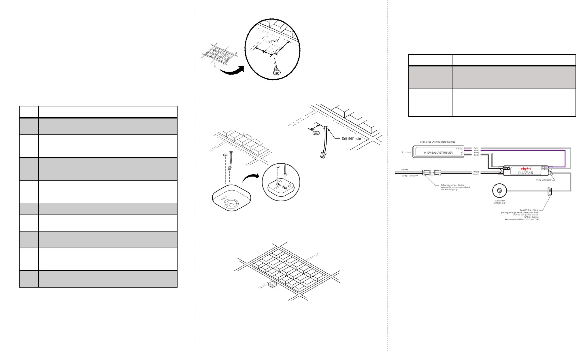
1 Turn off all power to the light fixture by switching off
the circuit breaker.
2
Mount the Control Unit (CU) in a UL approved
enclosure. Refer to the Control Unit Installation
Guide.
3 The Smart Sensor (SU-2O) should be mounted to the
ceiling within a few inches of the lighting fixture and
over the service area of the light. See Figure 2.
4 Select a place for the RJ12 data cable from the CU
to exit and make a small cut in the ceiling tile for
the cable to exit. See Figure 3.
5 Install the Smart Sensor anchor screw (as shown).
6 Connect the RJ12 data cable to the Sensor
(bottom entry). See Figure 4.
7 Slide the Smart Sensor onto the screw head as
shown. See Figure 4.
8 Slip the excess RJ12 data cable up into the plenum
area and adjust the ceiling tile to the original
position.
9 For wiring the sensor to the Control Unit, see Figure
6.
Installation
Figure 6: Wiring Drawing
Caution
• Installation and maintenance must be performed by a
qualified electrician in accordance with local, state, and
national electrical codes (NEC) and requirements.
Troubleshooting
Problem Solution
No green
flashing LED
lights
Verify that the RJ12 cable is plugged into the
Control Unit.
Red, flashing
LED
Possible solutions:
• Replace the RJ12 cable
• Replace the Enlighted Control Unit
To install the Enlighted Smart Sensor Unit, perform the following steps:
Figure 2: Sensor Distance from the Fixture
Figure 3: RJ12 Cable Exit
Figure 4: Sensor Connected to Anchor screw
Figure 5: Sensor Installed
 Loading...