ii ) Use a snap punch or other type of center punch to prevent the
drill from wandering. Drill a pilot hole with a smaller drill before
using a step drill bit.
iii ) Use only UL-listed rain-tight conduit tting for wire entry into
the enclosure.
B ) Planning the wiring:
The control wiring has three basic components:
i ) The signal wires (blue, orange, black, red) within the control cable.
ii ) The drain cable of the shield (marked as drain in Figure 3).
iii ) Termination resistor.
C ) Conrm if the Communications Kit 2 is the terminal node
A terminal node is a product (IQ Battery 5P, IQ System Controller
3/3G, or an IQ Gateway/IQ Combiner with a Communications Kit 2)
in the EES at the extreme end of the control wiring sequence. The
possible sequences for the whole system are dened in section 3 of
this document.
If the Communications Kit is a terminal node per our system wiring
diagram below, leave the termination header installed on the control
header. If the Communications Kit is not the terminal node, remove
the termination resistor to prepare the control header for wiring to
another node.
E ) Routing the control wiring
If the Communications Kit 2 is a non-terminating node, bring the
two sets of control wires into the Communications Kit 2 enclosure
through the bottom conduits. Use the zip ties provided to hold the
leads rmly in place.
If the Communications Kit 2 is a terminating node, then only one wire
leads into the Communications Kit enclosure. The other will contain
a termination resistor that is pre-installed.
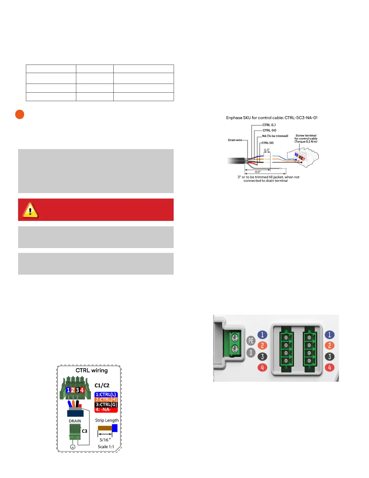
F ) Connecting the control wires to the control headers
The various ports and other components are shown in Figure 5.
There are also wiring diagrams in the following pages that can be
referred to for validating the wiring.
D ) Strip the cables for the connection
A ) Drill holes to accept the conduit
i ) The bottom of the Communications Kit enclosure is the best place
to drill holes for conduit ttings.
2
Control cable torque details:
Cable type Wire size Torque
Power cables 18 AWG 0.2 N m (1.77 lb-in.)
Ground cables 18 AWG 0.2 N m (1.77 lb-in.)
Terminal block cables 6 to 24 AWG 0.5 N m (4.42 lb-in.)
✓
NOTE: The control cables and the USB can go together in
the same conduit. However when the Communications Kit
2 is installed in a separate enclosure from the IQ Gateway/
IQ Combiner variants or Envoy S Metered, the cables used to
power the gateway, and the USB cable connecting the gate-
way to the Communications Kit 2 should be routed through
dierent conduits.
WARNING! Risk of equipment damage. Do not drill conduit
holes on the top of the box or at any location that allows
moisture ingress.
✓
NOTE: Make sure that the holes do not interfere with the inter-
nal workings, mechanics, or the deadfront legs in the corners
of the Communications Kit 2.
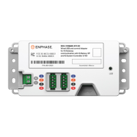
• Enphase control cables (sold separately; SKU: CTRL-SC3-NA-01).
Use Enphase control cables and headers for control wiring. En-
phase control cables are certied under UL-1277, UL-3003, and UL-
83. Enphase has validated performance using the Enphase control
cables. Enphase cannot guarantee performance when a third-party
cable is used.
Product installation and wiring
Figure 4: Control cable strip length
Figure 5: Control header view on control adapter
✓
NOTE:
Best practice is to
use a stepped drill bit to make the conduit
holes. Using a hole saw may crack the plastic housing. As an alterna-
tive, use a sharp chassis punch with caution.
Figure 3: Control header connection
i ) Connect the CTRL L (blue) to port 1 on the CTRL header.
ii ) Connect the CTRL H (orange) to port 2 on the CTRL header.
iii ) Connect the CTRL G (black) to port 3 on the CTRL header.
iv ) Trim the NA (red) wire.
v ) Terminate the drain wire only on one end of the cable (do NOT
terminate on both ends). If the terminating end is in the Com-
munications Kit 2, connect it to the drain port on the shield
header.
 Loading...