G ) Grounding the Communications Kit 2
From the potential earth port on the Communications Kit 2, there is a
pre-wired cable connected to the pre-installed ground terminal. Draw an
appropriately sized wire from a panel/IQ Combiner/IQ System Controller
to ground the ground terminal inside the Communication Kit 2.
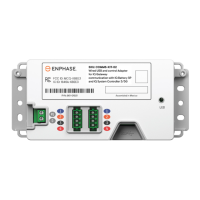
Figure 6: Control wiring for non-terminating node
Figure 7: Control wiring for terminating node
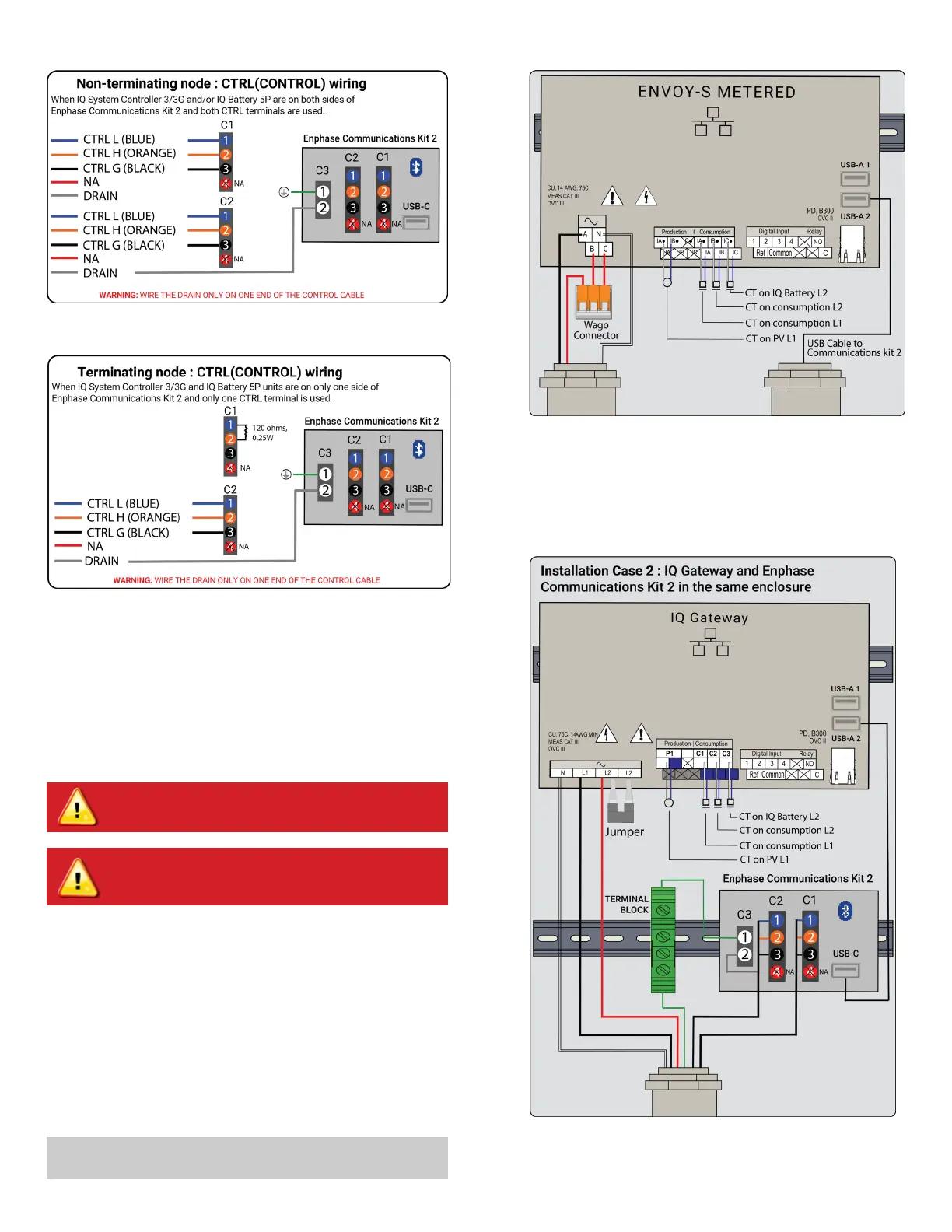
Figure 9: Wiring diagram when the IQ Gateway is installed in the Communi-
cations Kit 2 enclosure
I ) USB cable connection
If the IQ Gateway has been installed inside the Communications Kit
2 enclosure, connect the USB cable directly to the USB slot on the
IQ Gateway.
H ) Install CT for IQ Battery metering on the IQ Gateway
i. Short the L2 and L3 power terminals of the IQ Gateway using a
shorting jumper. If this is on an Envoy S Metered installation, short
the B and the C ports on the Envoy S Metered using a 3-pin Wago.
The ports currently support up to a 14 AWG wire, and a Wago of
appropriate size should be chosen.
ii. Clamp the IQ Battery CT on the line 2 power wire for all branches of
IQ Battery 5P (ensure that the L2 power terminal of the IQ Gateway
and the L2 power wire from the battery have phase continuity) with
the CT arrow pointing toward the load (away from the battery).
iii. Connect the CT lead wires to the C3 port on the consumption me-
ters on the IQ Gateway. (refer to Figure 9 for the wiring diagram). In
case of an Envoy S Metered, connect it to the IC
.
and IC consump-
tion ports as shown in Figure 8.
✓
NOTE:
Ensure that the jumper is used to short the two L2 terminals
on the IQ Gateway to not aect readings from the battery CT.
WARNING! Ensure the power to the IQ Gateway is turned o
via the breaker.
WARNING! Ensure the DC switches of the IQ Batteries are
turned o and the AC breaker to the IQ Batteries are turned
o.
Figure 8: Envoy S Metered wiring
 Loading...