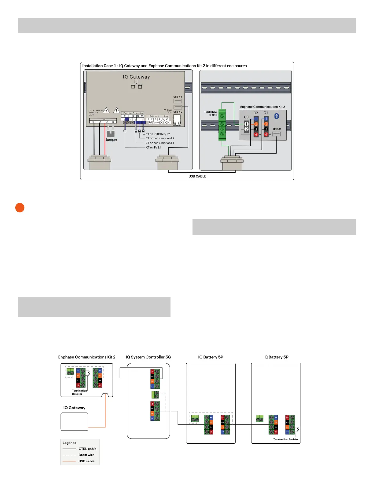
Control (CTRL) wiring between system components and Communications Kit 2
When installing the control wiring for the system, refer to the follow-
ing wiring sequences to best understand the termination resistor
header position, control wiring order, and drain wire termination
location.
The sequences below do not aect the functioning of the Communi-
cations Kit 2. They are the possible sequences that can occur, given
the potential limitations of the physical location the site is installed.
The choice of the sequence will indicate the location of the termi-
nation node, which will have to be kept track of to wire the product
correctly.
• One header with a termination resistor should be installed on each
component at the extreme end of the control network.
• The drain wire should only be terminated on one end of the control
wiring between system components.
• It is recommended that the drain wire be terminated at the compo-
nent from which the control wiring for the section is initiated.
• The same conduits can be used for power and control wire routing
only when using Enphase CTRL cable, CTRL-SC3-NA-01.
3
✓
NOTE: Ensure that the following guidelines are followed to avoid
system failures during commissioning:
Sequence 1: Enphase Communications Kit 2 - IQ System Controller 3G - IQ Battery(s) 5P
The following are the ve common wiring sequences:
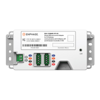
Figure 10: Wiring diagram when the IQ Gateway is installed in a dierent enclosure
If the IQ Gateway has not been installed inside the Communications Kit 2 enclosure or this is being used to upgrade an IQ Combiner 3 or 4 system to work
with IQ Battery 5P and IQ System Controller 3/3G, then draw the USB cable outside the Communications Kit 2 enclosure and into the enclosure housing
the IQ Gateway.
✓
NOTE: If using IQ Gateway in a dierent enclosure or a legacy IQ Combiner, ensure that a separate conduit is used so that the USB cable does not
use the same conduit as the power lines in the other enclosure.
✓
NOTE: Total length of control wiring across the system
should not exceed 250 feet to ensure the system operates
as per specications.
 Loading...