Method A // Use the included power cord
A ) Locate an AC socket that is indoors (or outdoors in an
IP54-rated enclosure) and close to the switchboard. If out-
doors, the socket must be appropriately rated.
B ) Plug the AC power cord into the AC inlet on the Envoy-S.
C ) Plug the other end of the power cord into a dedicated
230 VAC socket (not a power board).
Method B // Hardwire the Envoy-S for power
A ) Use a single-pole/Ph+N, 20 A maximum circuit break-
er for the supply wiring.
B ) Make sure supply wiring is 1.5mm
2
rated at 75 de-
grees C or better.
C ) Locate the screw on the left side of the terminal block
door, and loosen it with a screwdriver to unlock the
door.
D ) Flip open the terminal block door and move the shutter
to the left. Connect Line (active) to A and Neutral to N.
Tighten to 0.56 Nm.
E ) Close the terminal block door, and secure it with the
screw.
F ) Turn on the circuit feeding the Envoy-S.
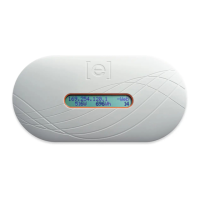
With all methods
All four LEDs ash amber during boot up (approximately
3 minutes). When boot up is complete, the Microinverter
Communications LED lights solid amber, indicating
that microinverters are not yet detected.
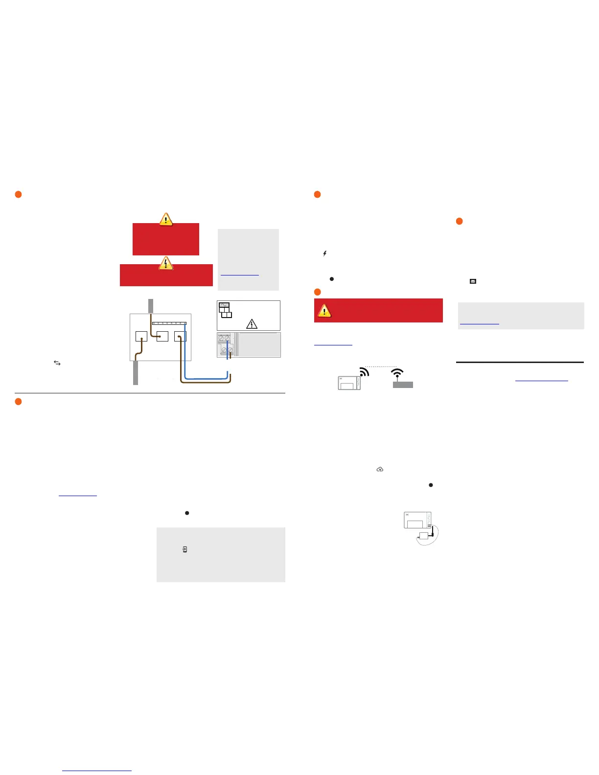
Provide a Power Connection
You can use the included AC power cord or terminal blocks to provide a power connection for the Envoy-S. If you wire the terminal block
connections, you must use a protected route using conduit for the wires to the Envoy-S.
DANGER! Risk of electric shock. Always
de-energise circuits before beginning wiring.
Detect Microinverters
Use one of the following methods to detect microinverters.
Method A // Provision microinverters with Installer Toolkit
Use the Installer Toolkit mobile app to congure the Envoy-S with the serial
numbers of the installed microinverters.
A ) Launch Installer Toolkit and tap View Systems.
B ) Select the system you are working with, or tap [+] to add a system.
C ) Connect to the Envoy-S with your mobile device as described in the
note at the bottom of this page.
D ) Return to Installer Toolkit. If the serial number for the Envoy-S you are
installing is not displayed on the System Overview screen, tap the [+]
next to the word “Envoys”. When the app displays the serial number of
the Envoy-S, tap it to add it to the system.
E ) Create the arrays and use your mobile device to scan the serial
numbers from the installation map as instructed by the Installer Toolkit
Operation Manual at enphase.com/support.
F ) Tap the Connect button. This provisions the scanned microinverters
on the Envoy-S.
G ) When prompted, conrm the number of microinverters that you in-
stalled.
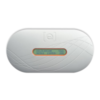
The Microinverter Communications LED lights solid green if all of the pro-
visioned devices are communicating or solid amber if any devices are not
communicating.
Method B // Discover microinverters with Installer Toolkit
Use the Installer Toolkit mobile app to set the number of microinverters the
Envoy-S should search for on the power line.
A ) Connect to the Envoy-S with your mobile device as described in the
note at the bottom of this page.
B ) Launch Installer Toolkit and tap Connect to an Envoy.
Note: Connecting to Envoy-S with a Mobile Device
The Envoy’s AP (Access Point) Wi-Fi network allows you to connect
your mobile device (smart phone or tablet) to the Envoy-S. The AP
Mode LED lights solid green when the network is available.
•
On the Envoy-S, if the AP Mode LED is not lit, press the AP
Mode button.
•
On your mobile device, go to Settings and join the Wi-Fi net-
work “Envoy_nnnnnn” (where “nnnnnn” represents the nal six
digits of the Envoy serial number).
C ) When prompted, enter the number of microinverters that you installed.
D ) When prompted to start a device scan, tap OK.
The Microinverter Communications LED ashes green while scanning.
It lights solid green when all of the microinverters you installed are commu-
nicating or solid amber if any devices are not communicating.
Method C // Discover microinverters with the Envoy-S
If you are not using the Installer Toolkit app, press the Device Scan button
on the Envoy-S. With this method, the Envoy searches the power line
for 15 minutes, but does not know how many microinverters it should
discover.
The Microinverter Communications LED ashes green for 15 minutes
while scanning. At the end of the scan, it lights solid green if at least one
microinverter was discovered or solid amber if no microinverters were
discovered (or if any discovered microinverter stops communicating).
With all methods
If the Microinverter Communications LED remains solid amber, see
Troubleshooting
b
.
2
3
Do not plug the Envoy-S into a
power board, surge protector,
or uninterruptable power supply
(UPS). These devices impede
power line communications.
Switchboard
Output from
PV System
L: brown
N: blue
N
A
CU,1.5 mm
2
, 75C
MEAS CAT III
OVC III
C
B
To Grid
WARNING: Do not remove power from the Envoy-S if
the LEDs are ashing green. This indicates that a soft-
ware upgrade is in progress.
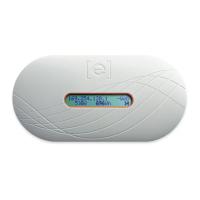
Within three minutes the Network Communications LED lights solid green,
indicating a successful connection to Enlighten. If the Network Commu-
nications LED remains off or lights solid amber, see Troubleshooting in the
Enphase Mobile Connect Installation Guide.
Send System Summary Report
When you have completed your system setup, you can generate and
email a summary report.
A ) From Installer Toolkit, tap Done in the upper-right corner of the screen
to disconnect from the Envoy. Installer Toolkit will ask if you want to
view a summary report.
B ) Tap View Report. The report displays Envoy and system information
with a list of microinverter serial numbers, their last power reports, and
information about the grid prole applied to the microinverters.
C ) Tap to email the report as needed as a record of successful sys-
tem installation and for evidence of grid prole settings.
Register the Envoy-S in Enlighten (enlighten.enphaseenergy.com).
Method A // If the Envoy-S is associated with a system in Installer
Toolkit
A ) On your mobile device, go to Settings and disconnect from the En-
voy’s Wi-Fi network.
B ) Return to the Installer Toolkit app and tap the Sync button on the
System Overview screen.
C ) When you have access to a computer, log in to Enlighten and select
the system name from the Activation List on the dashboard.
D ) From the activation form, open Array Builder.
If you used Installer Toolkit to build arrays and scan microinverter serial
numbers, the array(s) are built —make any necessary adjustments in Array
Builder.
If you did NOT use Installer Toolkit to build arrays and scan microinverter
serial numbers, create the virtual array in Array Builder, using the instal-
lation map as your reference. (You may need to wait if the microinverters
have not yet reported to Enlighten.)
Method B // If the Envoy-S is NOT associated with a system
in Installer Toolkit
A ) Log into Enlighten and click Add a New System from the dash-
board.
B ) Enter the System, Installer, Owner, and Location information.
C ) Enter the Envoy serial number.
D ) Click Save to submit the form.
E ) After the microinverters have reported to Enlighten, open Array
Builder from the activation form, and create the virtual array using the
installation map as your reference.
Verify System Conguration
While still connected to the Envoy-S with Installer Toolkit, check the Over-
view screen for the following:
A ) Conrm that the expected number of devices are detected and com-
municating.
B ) Tap the Grid Prole row on the Overview screen to select and apply
a grid prole to the microinverters. On the Overview screen, check that
the new prole is set on all the microinverters. This may take up to 5
minutes for a typical system.
If you used Installer Toolkit to detect microinverters, the Power Production
LED lights solid green when all expected microinverters are producing
power. If you did not use Installer Toolkit, it lights solid green if all commu-
nicating microinverters are producing power. It ashes green when
microinverters are upgrading. Check Installer Toolkit for production status
details. If the Power Production LED remains solid amber, see Trouble-
shooting
c
.
Connect to Enlighten
This section describes using the Envoy-S integrated Wi-Fi or the Mobile
Connect modem. For information about using Ethernet PLC bridges, refer
to the Enphase Envoy-S Installation and Operation Manual at:
enphase.com/support.
Method A // Integrated Wi-Fi
Requires a wireless router with an Internet connection.
A ) On the Envoy-S, verify that no Ethernet cable is plugged into the RJ45
port.
B ) If the router supports WPS, press and hold the WPS button on the
wireless router for a few seconds. On most routers, a WPS indicator
begins ashing.
C ) If you are using the Installer Toolkit mobile app, tap the Network
button, tap Wi-Fi, and then tap your network from the list of available
networks. If the wireless router does not support WPS, you may be
prompted to enter a password.
If you are not using the Installer Toolkit mobile app, initiate a WPS
connection by pressing and holding the Envoy-S AP Mode button for 5
seconds.
The Network Communications LED begins ashing green. Within
three minutes the Network Communications LED lights solid green,
indicating a successful connection to Enlighten. If the Network Communi-
cations LED remains off or lights solid amber, see Troubleshooting
d
.
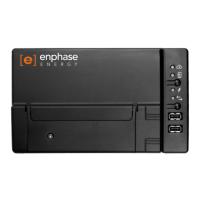
Method B // Enphase Mobile Connect Modem
(Order CELLMODEM-02 separately)
A ) Connect the antenna to the antenna
connector (marked CELL) on the modem.
B Mount the modem as described in the
Enphase Mobile Connect Installation
Guide.
C ) Connect the micro-USB cable to the
modem and connect the other end of the
cable to the Envoy-S. If receiving power
from the Envoy-S, the modem power LED lights.
ACTIVATE MONITORING
6
5
4
wireless router
Envoy-S
Enphase Mobile
Connect
modem
Envoy-S
Note: If you connect to an Envoy after associating it to a system, the
report includes a system name and address. For more information, refer
to the Enphase Installer Toolkit Operation Manual at:
enphase.com/support.
If you are installing the
Envoy-S in a multi-phase ap-
plication, install a phase coupler
on the load side of the over-cur-
rent protection device. For more
information, see the Technical
Brief on Phase Coupling
for your region at
enphase.com/support.
 Loading...