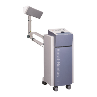
The Radarmed 650 is a microwave therapy unit designed for medical applications, operating at a wavelength of 12 cm (2450 MHz). It utilizes the great advantage of microwave treatment, which lies in the safety of its intensity setting, making it suitable for patient's sensation of warmth.
Function Description
The device is equipped with an operating safety circuit that requires the intensity control to be set to zero before any treatment can be commenced. Should the H.F. plug be inadvertently withdrawn during treatment, the intensity is automatically set to zero immediately, and the operating sequence must be recommenced.
The Radarmed 650 is suitable for use with the circular-field, through emitter, and longitudinal-field emitters. The intensity can be adjusted step-less from about 5 to 150 watts, and the LED output power at the front panel meter assists the operator.
The electronic circuit of the Radarmed 650 is located on five modules:
- Display module: Displays the H.F. output of the Radarmed 650 unit. The signal used for measuring the H.F. output is fed into the display PC Board via the display interface PC Board. The display PC Board is a three-digit LED DC Voltmeter with a maximum resolution of 1mV.
- Display interface module: Adapts the anode voltage measured at resistors R125 / R126 on the main PC Board. Both resistors are parallel mounted in the anode circuit of the magnetron. The measured voltage is related to the current which flows through the magnetron and therefore also related to the output power.
- Application module: The function of this module is to generate the output power to drive the magnetron. It comprises power supply circuits, fuses, and output stages.
- Distributor module: Selects and distributes the high voltage required for the magnetron, supplied by the high voltage transformer TR2.
- H.F. output module: Generates the H.F. output with a fixed frequency of 2450MHz (± 50 MHz). Its operation depends on two parameters: the charge of the buffer capacitor and the output voltage of the high voltage transformer TR2.
The mains power is fed into the Radarmed 650 via a mains entrance. Inside the mains entrance, two mains fuses are found. The mains power runs via a mains filter and a mains switch to the power supply PC Board. As soon as the equipment is switched on, the fan starts to run, and the magnetron is heated. The mains supply is fed via the mains configuration strip CNA (used for setting the magnetron heater voltage to 3.4V, see par. 4.6.1) into the primary side of the mains transformer TR1. The mains power is transformed into 9.7V (magnetron heater), 8.8V, +/- 9.7V, and fed into the power supply section of the main PC Board.
Important Technical Specifications
- Mains supply: 230 VAC ±10%
- Permissible mains voltage var.: 50-60 Hz
- Mains frequency: max. 3.5 A at 230 V
- Current consumption: 2 x T 6.3 A H 250 V
- Mains fuses: T 0.315 A (F103), T 0.5 A (F104), T 0.2 A (F105), T 1 A (F106)
- Internal fuses:
- Patient leakage current: Typical ≤ 10 µA (IEC requirement < 100 µA)
- Ditto, single fault condition: Typical ≤ 10 µA (IEC requirement < 500 µA)
- Earth leakage current: Typical 250 µA (IEC requirement < 500 µA)
- Ditto, single fault condition: Typical 500 µA (IEC requirement < 1000 µA)
- Earth resistance: 0.06 Ω (typical) (IEC601 requirement < 0.2 Ω)
- Safety class: I
- Safety approval: CE test Mark of TÜV Rheinland
- Radio interference suppression: IEC 601-1-2, EN55011 Group2 Class B, EN50082-2
- Dimensions: 50 x 40 x 93 cm
- Weight: 50 kg (excluding arm)
- Colour specification: EN Custom colours
- Operating frequency: 2450 MHz ± 50 MHz
- Channels: 1
- Mode of operation: Continuous
- High-freq. output power: Continuous H.F. max. 150 W at emitter
- Power indicator: LED at front panel up to 150 W
- Timer (mechanic): 0 - 30 min.; with acoustic signal and switch-off
Usage Features
The Radarmed 650 is designed for ease of use and safety. The step-less intensity adjustment and LED output power indicator allow for precise control during treatment. The safety circuit ensures that treatment only commences when the intensity is at zero, and automatically resets if the H.F. plug is disconnected.
Different emitters are available for various applications:
- Circular-field emitter: Approx. 10 cm minimum distance from the surface of the body. The circular-field emitter can be used on restricted body areas to effect deeper penetration. It is the most universal, and therefore the most used, emitter.
- Longitudinal-field emitter: Approx. 5 cm minimum distance from the surface of the body. The longitudinal-field emitter is used to treat long parts of the body, such as limbs.
- Through emitter: 0 cm minimum distance from the surface of the body. The through emitter is used to treat large areas. The special form of this emitter is well adapted to the appropriate body contours. Restricted regions, such as the shoulder and knee joints, can likewise be advantageously treated with this emitter, as can large muscular areas such as the pectoral girdle. For reasons of hygiene, a cloth should always be placed between the patient and emitter.
Maintenance Features
The service manual provides comprehensive instructions for maintenance, including:
- General checks: Visual inspection, electrical wiring for safety, component checks, fuse verification, and functional tests.
- Functional tests:
- Fan and display test: Connect the Radarmed 650 to the mains and switch on. The fan should start, and the air-flow should be correct. The magnetron should run without rattling. The three-segment LED output power display should light up and show "000".
- Treatment timer: Set a large (150 Watt) H.F. emitter to the Radarmed 650. Switch on and set a treatment time with the mechanical treatment timer. Turn the output power control fully anti-clockwise until the output control clockwise until the output power display reads "150" (Watt). Check that at the end of the treatment time the H.F. output switches off and the end of treatment signal is heard. The output power display should show "000".
- H.F. emitter detection circuit: Connect a large (150 Watt) emitter to the unit. Set treatment time (for example 5 min.) and start treatment. Check that there is H.F. output. Stop treatment by turning the output power control to zero. Disconnect the H.F. emitter cable from the unit (output impedance =). Turn the output power control clockwise and check the output power. Increasing the output power control will not result in increasing the H.F. output signal (display shows "000"), no H.F. energy is emitted.
- Magnetron Heater Voltage: Check the mains voltage at the mains distributor strip CNA. The heater voltage directly on the magnetron at the two blue leads should be between 3.37V and 3.43V.
- Supply voltage tests: Check the supply voltages with a multimeter with the negative testing lead to ST168 (ground terminal) at the main PC Board.
- Safety tests: Check the resistance of the earth connection and the earth leakage current in normal condition and single fault condition.
- Troubleshooting: A detailed troubleshooting list is provided for various failure indications, such as "Radarmed 650 does not switch on: LED displays fail to light, fan does not work" or "Fan works, display fails to light".
- Replacement procedures: Instructions for removing and installing various components like the front cover, top cover, Main PC Board, Display PC Board, Output power control potentiometer, Distributor PC Board, Magnetron / H.F. filter assembly, Mains transformer (TR1), High-Voltage transformer (TR2), and Cooling fan.
- Adjustment procedures:
- Magnetron heater voltage adjustment: Switch on the Radarmed 650 unit. Check the mains voltage at the mains distributor strip CNA. If the heater voltage is too low, shift the purple wire to the next higher connection at CNA. If the heater voltage is too high, shift the purple wire to the next lower connection at CNA.
- H.F. output power adjustment (using a moving-coil milliammeter in the DC range): Connect a large emitter to the output connector of the unit. Plug the voltage selector jumper CN3 (distributor PC Board) onto CN6 high-voltage tapping. Connect the moving-coil milliammeter in the cathode lead at connector CN4 at the distributor PC Board. Using a mains voltage of 230V / 50Hz, turn the output power control fully anti-clockwise and then clockwise until the H.F. output power display reads "100". Check that the current value read on the milliammeter corresponds to the value which is found on the magnetron/filter assembly for 100 Watts H.F. output power. Adjust the output power level by plugging the voltage selector jumper onto the next highest high-voltage tapping (if the output power level is not reached) or the next lower high-voltage tapping (if the output power level is exceeded). Fine-adjustment of the current is done by moving the slide over the wire wound resistor.
The Radarmed 650 is designed to be fully compliant with the IEC 601-1 (general standard), IEC 601-2-6 (microwave equipment), and IEC 601-1-2 (EMC) standards.