© COPYRIGHT 2016 ENTERGIZE, LLC. ALL RIGHTS RESERVED. P/N 71969 3220-2345 REV 00=E
4
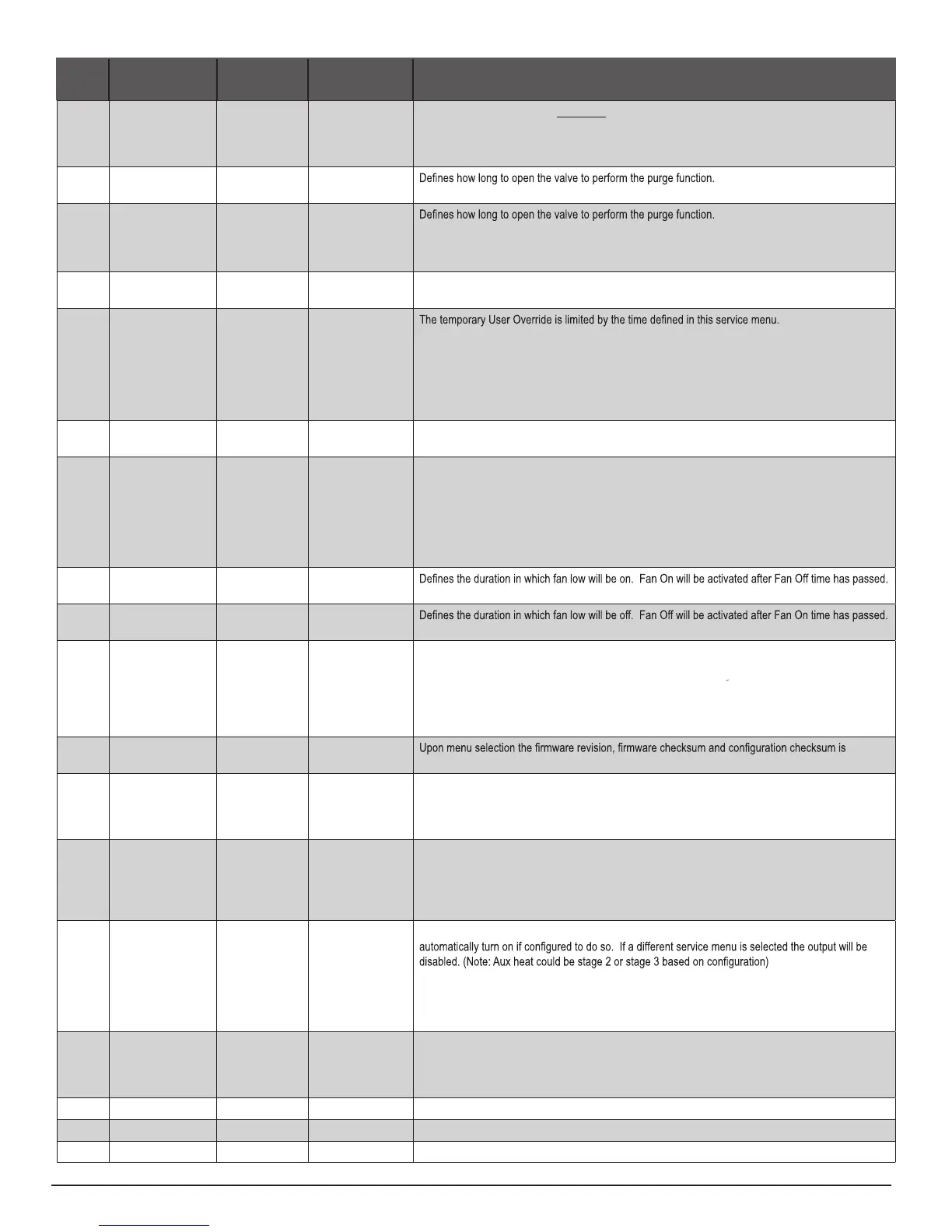
MENU FEATURE OPTIONS STD. DEFAULT DESCRIPTION / COMMENTS
375 Purge Enable 0-3 0 0 = No Purge
1 = W1 purge
2 = Y1 Purge
3 = W1 & Y1 purge
376 Purge Duration 1-3 1
1 to 3 minutes
377 Purge Frequency 0-2 0
0 = Every 24 Hours
1 = Every 12 Hours
2 = Every 6 Hours
380 Minimum Deadband
Adjustment
1-10°F, 0.5-5°C 3°F A changeover deadband value prevents short cycling between heating and cooling modes. The value is
adjustable to meet various HVAC system requirements.
395 Temporary Occupied
Duration Limit
0-4 hours 0
0 = Remainder of time until the next scheduled event.
1 = 1 Hour
2 = 2 Hours
3 = 3 Hours
4 = 4 Hours
480 Minimum Off Time Range:
0-10 Minutes
4 Sets the minimum off time for both the heat and cool output.
500 Programmable/
Intermittent Fan
0-2 0 In programmable mode, fan will operate continuously during occupied periods or with demand during
unoccupied periods. In intermittent mode, fan will operate based on the on and off times set in menus
501 and 502 whenever there is no call for fan.
0 = Disable
1 = Programmable Fan: Fan operates continuously in occupied periods or with demand in
unoccupied periods.
2 = Intermittent Fan: Fan operates based on the on and off times set in menus 501 and 502.
501 Intermittent Fan On
Time
1-60 minutes 5 minutes
502 Intermittent Fan Off
Time
0-60 minutes 25 minutes
A selection of 0 will result in continuous Fan.
520 Default Display
Icons
0-4 0 Select icons that will be displayed in the Default Display screen.
0 = Time, Temp, SP
1 = Time, Temp
2 = Time only
3 = Temp only
4 = No Display
530 Revision — —
displayed.
540 Factory Default
Reset
0,1 0 When Enable is selected the device will return to factory default settings.
0 = Disable
1 = Enable
Note: Press “Done” key to complete process.
600 System Test Main
Output (Cool)
0-2
0
If either stage is enabled it will activate the associated output for 10 minutes. The Fan output will
automatically turn on. If a different service menu is selected the output will be disabled.
0 = Disable
1= Cool Stage 1
2 = Cool Stage 2
610 System Test Main
Output (Heat)
0-3 0 If either stage is enabled it will activate the associated output for 10 minutes. The Fan output will
0 = Disable (Default)
1 = Heat Stage 1
2 = Heat Stage 2
3 = Heat Stage 3
620 System Fan Test
Output
0-3 0 0 = Disabled
1 = Low Speed
2 = Medium Speed
3 = High Speed
900 Factory Use Only -- -- Factory Use Only
901 Factory Use Only -- -- Factory Use Only
902 Factory Use Only -- -- Factory Use Only
WARNING: Service Menu 375 may disable fan operation during valve
purge. This feature should be set to 0 (zero) unless outputs are connected
to hydronic heating or cooling valves. Failure to follow this instruction can
result in damage to equipment and/or property.
▲
!
 Loading...