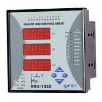
POWER FACTOR CONTROLLER
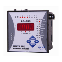
RG-B/BS
DIMENSIONS
Do not use device without checking terminal connections.
CONTROLS and OPERATIONS
Capacitor values are recognized and saved with ASEt operation. For doing this, enter
program menu at device and find ASEt menu. ASEt menu includes 2 parameters
which are S-oF and S-on.
When selection S-on and pressing SET button; firstly device try to find connection
failures (such as wrong connection at voltage and current inputs) then recognize all
capacitors steps. If 10th program (PS-10) is selected, all capacitors power will be
measured. In other programs, only first capacitor step power is measured and other
capacitor steps are calculated and recorded according to selected program. During
capacitor recognition, S-oF is selected and pressing SET button, automatic recognition
will be ended.
Note: After this process, calculated power values of all capacitor steps always
must be controlled. In order to have correct power values for capacitor steps,
current and voltage transformer ratios must be entered correctly. If current and
voltage transformer ratios are not entered, these ratios are supposed to be 1
and capacitor powers are calculated according to these values.
(Refer to VT and CT ratio settings).
Note: If automatic setup is selected as S-on, automatic mode starts immediately
without waiting to escape from the menu.
Automatic Capacitor Recognition and Phase Setup Mode
1
For proper operation, current and voltage connections must be connected as
shown in the connection diagram.
After current and voltage terminal connections, capacitor steps connection must
be done according to the connection diagram.
Lastly, computer communication connection must be done.
Do not power-up the device before verifying terminal connections.
1. RG-B/BS Connection
a)
b)
c)
d)
Device can detect wrong connection on the way of active power. For correcting connection
fault, automatic setup must be mode or in transformer menu there is a sub-menu named
AngL, which is programming phasor angle, suitable phase value must be programmed from
here. When user do automatic setup (ASEt), device will open and close 3 phase capacitor
in 1st step during correction of connection failure. Sudden changes in loads and nonlinear
loads (Thyristor or triac controlled frequency inverter, UPS etc.) existing, automatic setup may
not be done. In this condition, user should disconnect the device and restart it and make the
same operation. This operation can do with selecting S-on under ASEt menu. In this case
device corrects the errors and then calculates the capacitor values.If user does not want
calculating capacitor values, selecting S-oF parameter provides this.
User must be enter capacitor values after entering current and voltage transformer ratios.
Capacitor values can be calculated automatically or maually. Devices ASEt selecting
S-on (for details please look Operating Mode Settings) capacitor values will be entered
automatically. If 10
th
program (PS-10) is selected in program menu all capacitor values are
measured by switching on/off of the capacitors in sequence. In this program 3 phases capacitor
can be connected, without any connection rule, for network needing. If user did this application
just like at previous step, does not have to do this step. Selecting other program condition
device only calculate 1st step and other steps will be calculated according to selecting
program.
Device calculates the capacitor values which will be switched ON according to selected
program; so device switches ON / OFF the required steps.
Connection of circuit breaker or automatic fuse between the network and RG-B/BS is
highly recommended. Circuit breaker must be in close proximity to the device.
All used fuses must be FF type and the current values of the fuses must be 2A or 3A
and 6A (Refer to Connection Diagram).
Generator input must be done only when the network is supplied by the generator. Otherwise
device will be switched to the generator position for each generator starts including the
maintaining purpose.
a)
b)
c)
d)
e)
2.
Commissioning
RG-B/BS
Generator Input
When 110-250 V AC connection is connected to devices generator input COS1
position will be at passive, COS2 will be at active position. So, compensation will
do on target COS2 during voltage cut at this input.
CONNECTION DIAGRAM
Press SET button and enter ASEt menu (S-oF is displayed)
Select S-on option by scrolling UP/DOWN buttons.
(This parameter should be selected as ON in order to start the
Automatic Capacitor Recognition.)
Press SET button in order to activate your selection.
Press SET button 3 sec. and select Auto option.
Select ASEt parameter by scrolling UP/DOWN buttons.
Operating Mode (Automatic/Manual Mode) Settings
RG-B/BS has two operating modes which are automatic mode and manual mode.
Operating mode can be selected by selecting A-on (automatic) or A-oF (manual)
option. Manual mode is used for test purpose. In this mode, capacitor steps are
switched on&off and so relay outputs of the device are tested. In the manual mode,
capacitor steps are switched on by pressing SET button and also capacitor steps
are switched off by pressing ESC button. Factory set values for switching on (ond)
and switching off (oFd) time is 10 sec. These time values can be programmed in the
Delay (dELy) menu (Refer to delay time setting). In the manual mode, step numbers,
which will be switched on&off, can be programmed in Step menu (Refer to step
number setting). Even if manual mode is selected, after 5 minutes, device starts to
work in automatic mode and continues to operate in automatic mode.
When automatic mode is selected, AUTO/MAN LED lights on continuously.
When manual mode is selected, AUTO/MAN LED blinks.
Warning: Device warns user by blinking (short ON, long OFF) the capacitor steps
which will be switched on. Also device warns user by blinking (long ON, short
OFF) the capacitor steps which will be switched off.
For switching capacitors; voltage inputs must be connected and measured
voltage must be higher than (min. 0.5 multiple) programmed nominal network
voltage.
* Current value of 3-Fuses, which are connected to protect the capacitors, is
chosen according to the nominal current value of capacitors.
** At 3 phase 4 wire applications L1 and Neutral must be connected devices
voltage measurement inputs, at 3 phase 3 wire applications L2 and L3 phases
must be connected. L1 phases current transformer must be connected to
current measurement input. If load is unbalanced, current cable which is
nearest value of total average value must be connected to current transformer.
In this condition voltage inputs must be set refer to current. When device
programmed to automatic setup, it will program suitable phase angle. So it
will measure true values and true compensation.
Precautions for Safe Use and Installation
This user manual is prepared for quick commisioning and operating
of the device. Please read this manual carefully before commisioning
or operating RG-B/BS
Maintenance, installation and operation of RG-B/BS must be performed only by
the qualified technicians.
RG-B/BS is connected to the network with current transformer. Do not disconnect
the current transformer terminals. If you disconnect them, be sure to short-circuit
or connect them to another parallel load which have low impedance.
In case of failure, dangerously high voltage at the secondary side of current
transformer may cause an electric shock.
Device is suitable only for panel mounting.
Verify terminal connections when wiring.
Do not use this product for any other purpose than its original task.
Do not operate undervoltage.
When device is connected to the network, do not remove the front panel.
Do not open the RG-B/BSs housing. There are no user servicable parts inside
it.
Do not clean the device with solvent or similar items. Only clean with a dry cloth.
Electrical equipment should be serviced only by your competent seller.
1)
2)
3)
4)
5)
6)
7)
8)
9)
10)
No responsibility is assured by the manufacturer or any of its subsidiaries
for any consequences arising out of the use of this material.
1) Panel cut-out dimension must be 91 mm x 91 mm for Type PR19 and 143 mm x
143 mm for Type PR16.
2) Before installation, remove the mounting brackets.
3) Mount the device to front panel.
4) Insert the mounting brackets.
5) Wire thickness for voltage and current terminals must be 2,5 mm
2
, but it is suitable
for cables which have up to 4 mm
2
section.
6) CAT5 cable is recommended for RS-485 input terminal.
Excessive force can damage to the device.
Turn the screw into the terminals and tighten until the RG-B/BS is secured in
place.
70mm
79.3mm
90mm
96mm
96mm
Type PR 19
15 17 18 19 20 21 22
5 6 9 10
6A
Alarm Relay
11 12
C1 C6 C7 C12
23 24 25 26 27 30 31 32 33
N
L3
L2
L1
Fan Relay
13 14
1 2 3 4
Un V
in
I
in
Generator
Input
110~250 V AC
16
1A
K L
l1k1
~ ~
TR B GNDA
RS485
L2
L3
****
Type
PR16
(144x144)
143
99
121
138.4
143
18
34.5
67
RG-6B/BS
RG-8B/BS
RG-12B/BS
RG-6B/BS
RG-8B/BS
****