Do you have a question about the Entes RGI-12W and is the answer not in the manual?
Product installation, commissioning, maintenance, and operation must be handled by authorized specialists.
Always disconnect all power sources before installing the device to ensure safety.
Never remove the front panel or connections while the product is connected to mains power.
Do not dismantle the product as it contains no user-serviceable parts; doing so voids the warranty.
Ensure product ventilation holes remain unobstructed for proper operation.
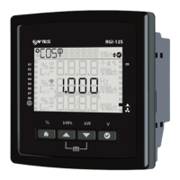
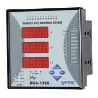
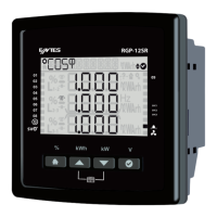
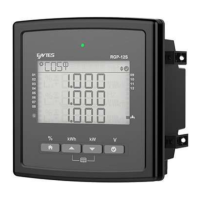
Details the primary functions and features of the RGI Series power factor controllers.
Provides detailed technical specifications for connections, ranges, and terminal types.
Provides step-by-step instructions for making the product's electrical connections.
Guides the user through the initial start-up process and parameter setup of the product.
Guides on performing automatic step recognition for optimal product configuration.
Allows selection of the power factor correction program (e.g., Linear, Capacitor/Reactor).
Defines the target CosФ value for power factor correction.
Configures Modbus RTU settings like address, bit rate, and parity.
Triggers an alarm when the inductive power factor rate exceeds the user-defined limit.
Alarms if the capacitor's power falls below a set limit.
Alarms when the switching count of contactors exceeds the set ratio.
Sets voltage alarms with high threshold, hysteresis, and optional step protection.
Alarms if the Current Total Harmonic Distortion exceeds the set threshold.
Resets all product settings and logs to factory defaults.
Resets the energy counter data saved on the product.
Outlines the 2-year warranty against manufacturing defects and void conditions.
| Brand | Entes |
|---|---|
| Model | RGI-12W |
| Category | Controller |
| Language | English |