Do you have a question about the Entes RGP Series and is the answer not in the manual?
Product overview, features, and capabilities.
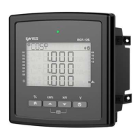
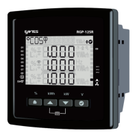
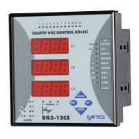
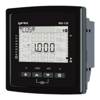
Details on different RGP models and their specifications.
Environmental and operational parameters for optimal performance.
Explains the meaning of various LED colors and statuses.
Describes the smiley face indicators and their operational meanings.
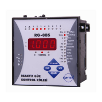
Identifies and describes components on the product's front panel.
Explains generator, temperature, alarm, and fan indicator symbols.
Quick access to power factor correction values for the month.
Quick access to active energy measurement screens.
Quick access to total power measurement data.
Quick access to phase-to-neutral voltage values.
Information on using the interactive tutorial mode.
Guide for initial language, region, and basic settings.
How to access and navigate the main settings menu.
Customizing user preferences like language, backlight, and security.
Adjusting initial setup parameters like frequency and CT settings.
Steps to correct electrical connection errors.
Configuring primary and secondary current transformer values.
Setting the nominal system frequency (50 Hz or 60 Hz).
Performing automatic step recognition and configuration.
Automatic setup for SVC components and recognition.
Defining steps, types, connections, and power.
Manually setting driver values for specific SR models.
Choosing the power factor correction program or mode.
Selecting between Eco, Sensitive, and Standard PFC modes.
Defining the desired power factor target value.
Setting the CosΦ target when the generator input is active.
Setting the delay for capacitor/reactor switching operations.
Setting the delay for capacitor/reactor release operations.
Setting reaction time for single-phase load changes.
Setting the minimum time after step release before re-switching.
Manually switching capacitor and reactor steps on/off.
Manually switching SVC reactor powers on/off.
Setting the day for electricity bill readings.
Setting Modbus address, bit rate, and parity.
Setting a delay for alarm notifications to avoid nuisance alarms.
Alarms and warnings for exceeding inductive rate limits.
Alarms and warnings for exceeding capacitive rate limits.
Alarms and warnings for capacitor power falling below limits.
Warnings for exceeding contactor switching count limits.
Alarms for exceeding contactor switching count limits.
Setting alarms for voltage exceeding thresholds.
Alarms for exceeding Total Harmonic Distortion (Voltage).
Alarms for exceeding Total Harmonic Distortion (Current).
Alarms for internal temperature exceeding limits.
Configuring user-defined special alarms.
Setting the product's local time zone.
Setting the current date on the device.
Setting the current time on the device.
Shows the current software version of the product.
Shows the current hardware version of the product.
Shows the unique serial number of the product.
Resets all product settings to their original factory defaults.
Resets the energy consumption counter data.
Shows today's inductive and capacitive power factor correction rates.
Shows yesterday's inductive and capacitive power factor correction rates.
Shows PFC rates for the past 7 days.
Shows PFC rates for the current month.
Shows PFC rates for the previous month.
Displays the Cos Φ value for each individual phase.
Displays the power factor value for each individual phase.
Displays total active, reactive, and apparent power values.
Displays active power values for each phase.
Displays reactive power values for each phase.
Displays apparent power values for each phase.
Displays active energy imported from the network.
Displays active energy exported to the network.
Displays the measured inductive reactive energy.
Displays the measured capacitive reactive energy.
Displays the measured apparent energy.
Displays energy generated when the generator input is active.
Displays phase-to-neutral voltage measurements.
Displays phase-to-phase voltage measurements.
Displays phase current measurements.
Displays the operating frequency of the product.
Displays the internal temperature of the device.
Displays current harmonic values up to the 31st harmonic.
Displays voltage harmonic values up to the 31st harmonic.
Displays the total harmonic distortion for current.
Displays the total harmonic distortion for voltage.
Physical dimensions and environmental operating limits.
Specifications for phase-neutral and phase-phase voltage measurements.
Specifications for phase current measurements.
Specifications for phase and total power measurements.
Specifications for active, reactive, and apparent energy.
Specifications for minimum and maximum measured values.
| Brand | Entes |
|---|---|
| Model | RGP Series |
| Category | Controller |
| Language | English |