EasyManua.ls Logo

Entes RGI Series User Manual

Entes RGI Series
56 pages
To Next Page IconTo Next Page
Page #1 background imageLoading...
Page #1 background image
1
Single Phase Power
Factor Controllers
RGI Series
RGI-12S
www.entes.com.tr

Table of Contents

Question and Answer IconNeed help?

Do you have a question about the Entes RGI Series and is the answer not in the manual?

Entes RGI Series Specifications

General IconGeneral
Frequency50/60 Hz
Communication ProtocolModbus RTU
MountingDIN Rail
Communication PortsRS-485
Protection ClassIP20
Weight200g

Summary

Safety Warnings

General Installation and Operation Safety

General safety guidelines for installation, operation, power disconnection, ventilation, and isolation marking.

Electrical Connection and Safety

Safety precautions for battery, connections, measurement inputs, capacitors, current transformers, and fuses.

Product Integrity and Usage Restrictions

Warnings regarding battery replacement, product dismantling, and intended use to maintain warranty.

1. Introduction

1.1 General Specifications

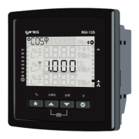
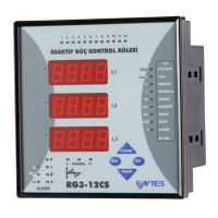
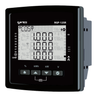
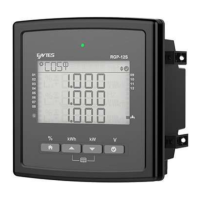
Overview of RGI series reactive power factor controllers and their capabilities.

1.2 RGP Product Family

Details product codes and specifications for the RGI product family.

1.3 Operating Conditions

Specifies the required operating voltage, frequency, temperature, and humidity.

1.4 LED Indicator

1.5 Display Smiley View

1.6 Front Panel View

1.7 Key Functions

1.7.1 Generator, Temperature, Alarm and Fan Indicators

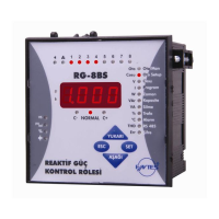
Describes indicators for Generator, Alarm, Fan status, and specific alarm icons.

1.7.2 Power factor correction Shortcut Menu

Details how to access power factor correction values for the current month.

1.7.2 Energy Shortcut Menu

Explains how to access instant energy parameters like active import/export.

1.7.3 Total Power Shortcut Menu

Details how to access the total power menu, showing active, reactive, and apparent power.

1.7.4 V L-N Shortcut Menu

Explains how to access the MEA TOTAL menu to view instant voltage values.

1.7.5 Tutorial Mode

1.8 Technical Specifications

Connection Diagram P-P

Connection Diagram P-N

1.10 Start-up the RGI Product

2. Using the Product

2.1 Setup

Details the initial setup process, including language selection and configuration screens.

3. Menus

3.1 Settings Menu

Explains how to access and navigate the Settings menu and its submenus.

User Settings Management

Setup Configuration

3.1.2.2 Current Transformer

3.1.2.3 System Frequency Settings

3.1.2.4 Auto Setup Setting

3.1.2.5 Step Setting

3.1.3 Power factor correction Settings

3.1.3.1 Power factor correction Program

Selects the power factor correction program (e.g., Linear, Capacitor/Reactor, Combination).

3.1.3.2 Power factor correction Mode

3.1.3.3 Target CosФ

3.1.3.4 Generator Target CosФ

3.1.3.5 Three-phase On Delay

3.1.3.6 Three-phase Off Delay

3.1.3.7 Discharge Time

3.1.3.8 Power factor correction Manual Step

3.1.3.9 Power factor correction Reading Day

3.1.4 Communication Settings Menu

Modbus Configuration Parameters

Configures Modbus address, bit rate, and parity for device communication.

3.1.5 Alarms Menu

3.1.5.1 Alarm Delay Time

Sets a delay time for alarm notifications to avoid immediate alerts.

3.1.5.2 Inductive Rate Alarm

Triggers an alarm when the inductive power factor rate exceeds a user-defined threshold.

3.1.5.3 Inductive Rate Warning

Triggers a warning when the inductive power factor rate exceeds a user-defined threshold.

3.1.5.4 Capacitive Rate Alarm

3.1.5.5 Value Loss Warning

3.1.5.6 Value Loss Alarm

3.1.5.7 Value Loss Warning

3.1.5.8 Contactor Service Life Warning

3.1.5.9 Contactor Service Life Alarm

3.1.5.10 Voltage Alarm

3.1.5.11 THDV Alarm

3.1.5.12 THDI Alarm

3.1.5.13 Temperature Alarm

3.1.5.14 Special Alarm

Fan Alarm

3.1.6 Time Menu

3.1.6.1 Time Zone

Allows setting the product's time zone within a specified range.

3.1.6.2 Date

3.1.6.3 Time

3.1.7 System Menu

3.1.7.1 Software Version

Shows the current software version installed on the product.

3.1.7.2 Hardware Version

3.1.7.3 Serial Number

3.1.8 Reset Menu

3.1.8.1 Restore Factory Settings

Restores all product settings and logs to their factory defaults.

3.1.8.2 Energy Counter Reset

Resets the saved energy counter data on the product.

3.2 COS Fi (Φ) Menu

3.3 Power factor correction Menu

3.3.1 Power factor correction Today

Displays today's inductive and capacitive power factor correction rates.

3.3.2 Power factor correction Yesterday

Displays yesterday's inductive and capacitive power factor correction rates.

3.3.2 Power factor correction Last 7 Days

3.3.4 Power factor correction This Month

3.3.5 Power factor correction Last Month

3.4 Power

3.4.1 Power Cos Φ

Displays the Cos Phi value of the system.

3.4.2 Power Factor

Displays the power factor of the system.

3.4.3 Total Power

Shows single-phase active, reactive, and apparent power values.

3.5 Energy

3.5.1. Active Import Energy (AI)

Displays the active import energy consumed by the system.

3.5.2. Active export energy (AE)

Displays the active export energy generated by the system.

3.5.3. Inductive reactive energy (Enr r)

Displays the inductive reactive energy consumed or generated.

3.5.4. Capacitive reactive energy (Enr r)

3.5.5. Apparent energy (S)

3.5.6. Generator Energy (Gen)

3.6 Measurements

3.6.1 Temperature

Displays the internal temperature of the product.

3.7 Harmonics

3.7.1 Current Harmonics

Displays current harmonics up to the 31st harmonic.

3.7.2 Voltage Harmonics

Displays voltage harmonics up to the 31st harmonic.

3.6.3 Current Total Harmonic Distortion (THDI)

Displays the Current Total Harmonic Distortion (THDI).

3.6.4 Voltage Total Harmonic Distortion (THDV)

Displays the Voltage Total Harmonic Distortion (THDV).

3.8 Messages

4 Maintenance

5 Warranty Terms

6 Conformity Data

7 Annexes

7.1 Mechanical and Environmental Conditions

Details physical dimensions, installation, protection, and environmental operating conditions.

7.2 Measuring

Provides specifications for various measurement parameters.

7.2.1 Voltage

Specifies voltage measurement parameters, ranges, and sensitivities.

7.2.2 Phase Current

Specifies phase current measurement parameters, ranges, and sensitivities.

7.2.3Power

7.2.4Energy

7.2.5Min&Max Values

7.3 Step

7.4 Time

Related product manuals