VD 950
Door Station
AC Input
2
2
2
2
2
2
POWER SUPPLY
PS-50/PS55
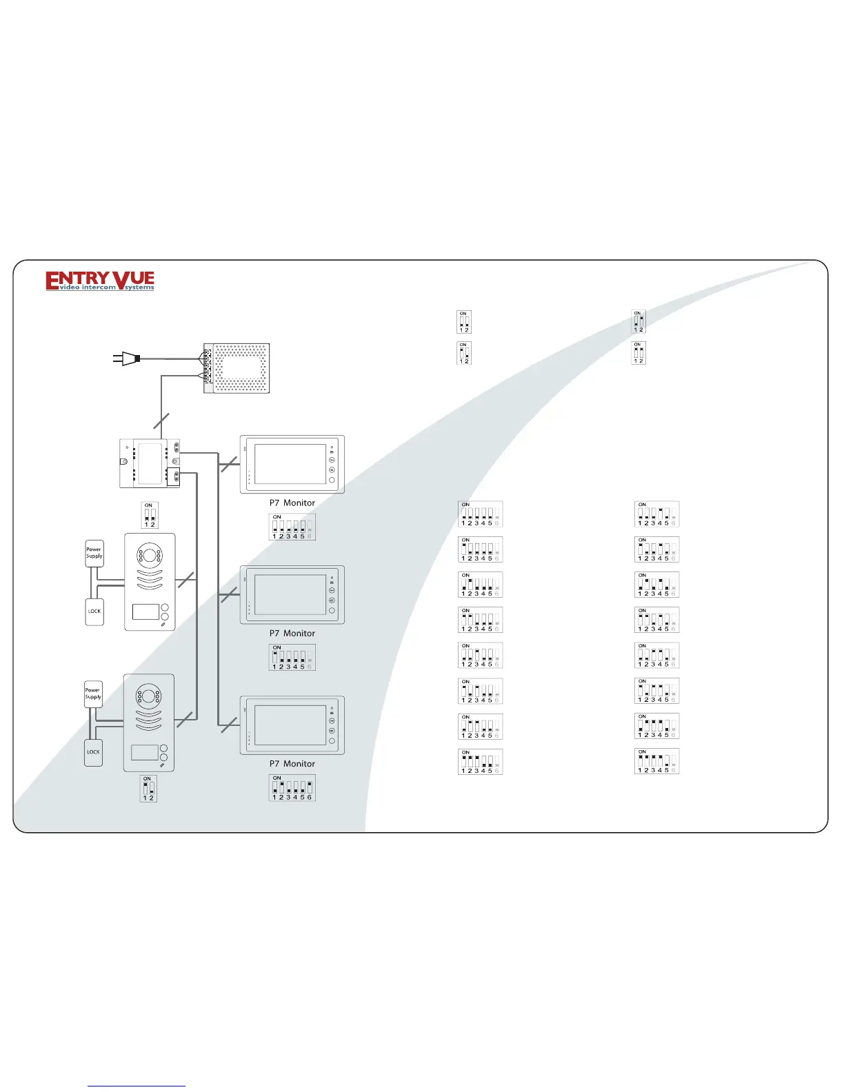
VD-950 WIRING DIAGRAM
DIP SWITCHES SETTINGS OF DOOR STATION:
FIRST DOOR STATION
SECOND DOOR STATION
THIRD DOOR STATION
FOURTH DOOR STATION
MONITOR 1 MONITOR 9
MONITOR 13
MONITOR 14
MONITOR 12
MONITOR 11
MONITOR 15
MONITOR 16
MONITOR 10
MONITOR 7
MONITOR 8
MONITOR 6
MONITOR 5
MONITOR 4
MONITOR 3
MONITOR 2
DIP SWITCHES SETTINGS OF MONITOR:
There are 6 Dip Switches in total,and each monitor MUST be
set with the correct code.
If daisy chain connection used,dip switch # 6 should be set
ON only on the monitor is at the end of the line.
If parallel connection used, all monitors should have the dip
switch # 6 set ON.
DPS
Dip switches 3 and 4 are inactive, so set them OFF.
For Door Station Model B, please refer to Dip Switches 17-32
on the next page.
Page 03