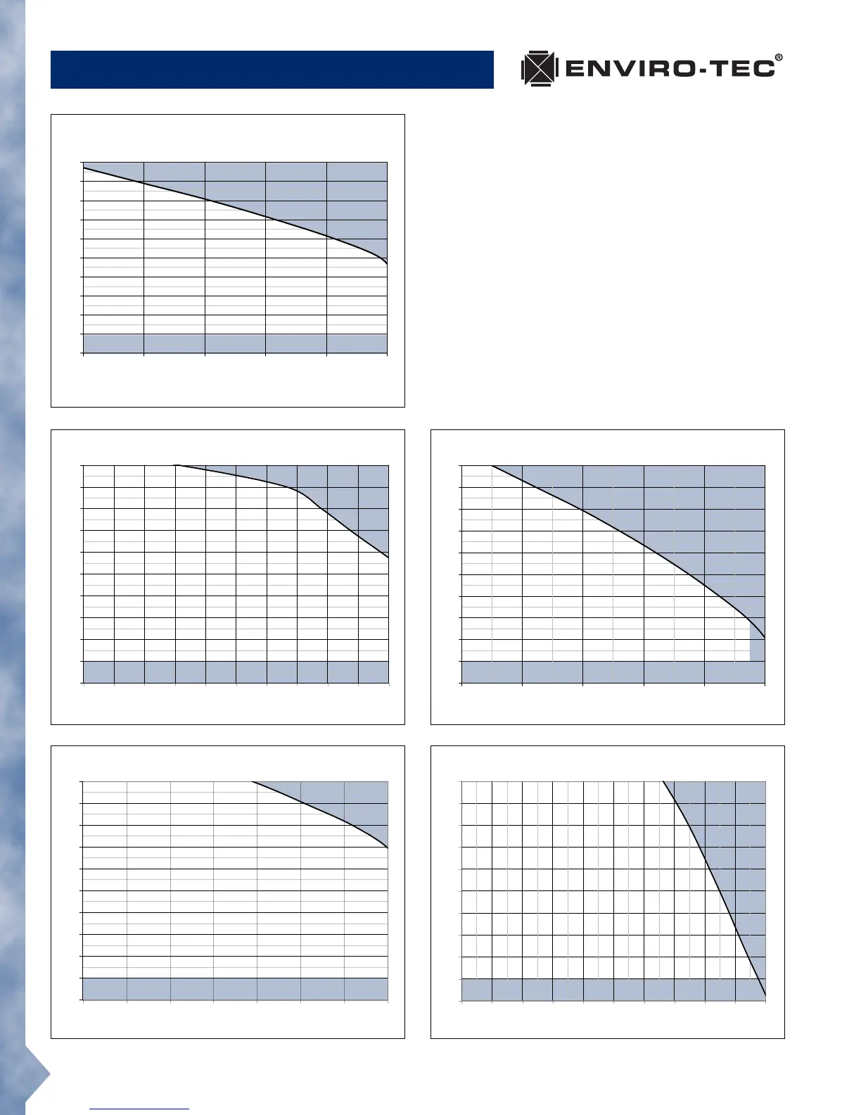
CFR • FAN PERFORMANCE, ECM™ MOTOR
20
CFR Catalog • ©December, 2005 Environmental Technologies, Inc.
UNIT SIZES 1021, 1221, 1421
0.0
0.1
0.2
0.3
0.4
0.5
0.6
0.7
0.8
0.9
1.0
600 800 1000 1200 1400 1600 1800 2000
AIRFLOW / CFM (Standard Density Air)
0.0
0.1
0.2
0.3
0.4
0.5
0.6
0.7
0.8
0.9
1.0
1500 1700 1900 2100 2300 2500 2700 2900 3100 3300 3500
AIRFLOW / CFM (Standard Density Air)
General Fan Note
The fan curves depicted on this page are for ECM™
type motors. Actual specified capacities which fall
below the fan curve can be obtained by adjustment
of the fan speed controller. Selections should only
be made in the non-shaded areas. The minimum
external static pressure requirement is shown for each
fan assembly. The unit fan should not be energized
prior to realizing this minimum external static pres-
sure.
Terminals equipped with a hot water heating coil
require the addition of the coil pressure drop to the
specified external static pressure before making the
fan selection.
UNIT SIZES 0611, 0811, 1011
0.0
0.1
0.2
0.3
0.4
0.5
0.6
0.7
0.8
0.9
1.0
150 300 450 600 750 900
AIRFLOW / CFM
(Standard Density Air)
UNIT SIZES 0818, 1018, 1218
0.0
0.1
0.2
0.3
0.4
0.5
0.6
0.7
0.8
0.9
1.0
500 600 700 800 900 1000 1100 1200 1300 1400 1500
AIRFLOW / CFM (Standard Density Air)
0.0
0.1
0.2
0.3
0.4
0.5
0.6
0.7
0.8
0.9
1.0
1400 1600 1800 2000 2200 2400
AIRFLOW / CFM (Standard Density Air)