CFR • ELECTRIC HEAT
22
CFR Catalog • ©December, 2005 Environmental Technologies, Inc.
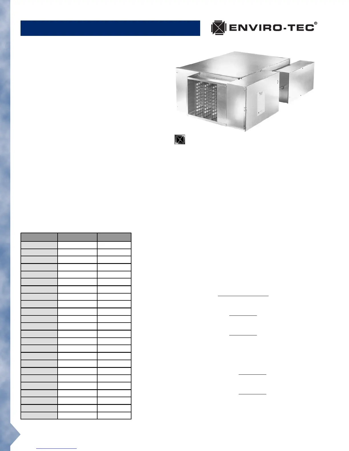
Model CFR-EH
Standard Features
• cETL Listed as an assembly for safety compliance
per UL 1995
• Primary auto-reset high limit
• Secondary high limit
• Hinged control panel
• Ni-Chrome elements
• Primary/secondary power terminations
• Fusing per NEC
• Wiring diagram and ETL label
• Fan interlock device (relay or P.E. switch)
• Single point power connection
• Available kW increments are as follows:
0.5 to 5.0 kW - .25 kW; 5.0 to 10.0 kW - .50 kW;
Above 10 kW - 1.0 kW.
Optional Features
• Disconnect (toggle or door interlocking)
• P.E. switches
• Mercury and magnetic contactors
• Manual reset secondary limit
• Proportional control (SSR)
• 24 volt control transformer
• Airflow switch
Selection Procedure
With standard heater elements, the maximum capacity (kW)
is obtained by dividing the heating (fan) SCFM by 70. In
other words, the terminal must have at least 70 SCFM per
kW. In addition, each size terminal has a maximum allow-
able kW based upon the specific heater element configuration
(i.e. voltage, phase, number of steps, etc.). Contact your
ENVIRO-TEC
®
representative or refer to the ENVIRO-TEC
®
Windows
®
based computer selection program for design
assistance.
Heaters require a minimum of 0.07" w.g. downstream
static pressure to ensure proper operation.
For optimum diffuser performance in overhead heating
applications, the supply air temperature should be with-
in 20°F of the desired space temperature. This typically
requires a higher air capacity which provides higher air
motion in the space increasing thermal comfort. The elec-
tric heater should be selected with this in mind, keeping
the LAT as low as possible.
Selection Equations
kW = SCFM x
ΔT x 1.085*
3413
CFM = kW x 3413
ΔT x 1.085*
ΔT = kW x 3413
SCFM x 1.085*
* Air density at sea level - reduce by 0.036
for each 1000 feet of altitude above sea level.
Calculating Line Amperage
Single Phase Amps = kW x 1000
Volts
Three Phase Amps = kW x 1000
Volts x 1.73
Maximum Allowable kW