CFR • GUIDE SPECIFICATIONS
30
CFR Catalog • ©May, 2006 Environmental Technologies, Inc.
GENERAL
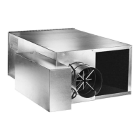
Furnish and install ENVIRO-TEC
®
Model
CFR, or equal, Series Flow Constant Vol-
ume Fan Powered Terminals of the sizes
and capacities scheduled. Units shall
be ETL listed. Terminals with electric
heat shall be listed as an assembly. Sep-
arate listings for the terminal and
electric heater are not acceptable.
Terminals shall include a single point
electrical connection. Terminal units
shall be ARI certified and bear the ARI
880 seal.
The entire unit shall be designed and
built as a single unit. Field-assembled
components or built-up terminals
employing components from multiple
manufacturers are not acceptable.
CONSTRUCTION
Terminals shall be constructed of not
less than 22 gauge galvanized steel,
able to with-stand a 125 hour salt spray
test per ASTM B-117. Stainless steel
casings, or galvannealed steel cas-
ings with a baked enamel paint finish,
may be used as an alternative. The ter-
minal casing shall be mechanically
assembled (spot-welded casings are not
acceptable).
Casing shall be internally lined with 3/4"
thick, 4 pound per cubic foot skin, dual
density fiberglass insulation, rated for
a maximum air velocity of 3600 f.p.m.
In addition to using adhesive complying
with NFPA 90A, the insulation shall
incorporate a secondary mechanical fas-
tener attached to the unit casing wall
(e.g. weld pin). Adhesive as the only
method of fastening the insulation to
the casing is not acceptable. Insula-
tion must meet all requirements of
ASTM Standards C1071, C1338, G21;
UL 181 and NFPA 90A. Raw insulation
edges on the discharge of the unit must
be covered with metal liner to elimi-
nate flaking of insulation during field
duct connections. Simple "buttering"
of raw edges with an approved sealant
is not acceptable.
Casing shall have full bottom access
to gain access to the primary air valve
and fan assembly. The opening shall
be sufficiently large to allow complete
removal of the fan if necessary. The
casing shall be constructed in a man-
ner to provide a single rectangular
discharge collar. Multiple discharge
openings are not acceptable. All
appurtenances including control assem-
blies, control enclosures, hot water heat-
ing coils, and electric heating coils shall
not extend beyond the top or bottom
of the unit casing.
SOUND
The terminal manufacturer shall pro-
vide ARI certified sound power data
for radiated and discharge sound.
The sound levels shall not exceed the
octave band sound power levels indi-
cated on the schedule. If the sound
data does not meet scheduled crite-
ria, the contractor shall be responsible
for the provision and installation of any
additional equipment or material nec-
essary to achieve the scheduled sound
performance.
PRIMARY AIR VALVE
The primary air valve shall consist of
a minimum 22 gauge cylindrical body
that includes embossment rings for
rigidity. The damper blade shall be con-
nected to a solid shaft by means of an
integral molded sleeve which does not
require screw or bolt fasteners. The
shaft shall be manufactured of a low
thermal conducting composite mate-
rial, and include a molded damper
position indicator visible from the
exterior of the unit. The damper shall
pivot in self lubricating bearings. The
damper actuator shall be mounted on
the exterior of the terminal for ease
of service. The valve assembly shall
include internal mechanical stops for
both full open and closed positions.
The damper blade seal shall be secured
without use of adhesives. The air valve
leakage shall not exceed 1% of max-
imum inlet rated airflow at 3” W.G. inlet
pressure.
PRIMARY AIRFLOW SENSOR
For inlet diameters 6" or greater, the
differential pressure airflow sensor
shall traverse the duct along two per-
pendicular diameters. Cylindrically
shaped inlets shall utilize the equal cross
sectional area or log-linear traverse
method. Single axis sensor shall not
be acceptable for duct diameters 6" or
larger. A minimum of 12 total pres-
sure sensing points shall be utilized.
The total pressure inputs shall be
averaged using a pressure chamber
located at the center of the sensor. A
sensor that delivers the differential pres-
sure signal from one end of the sensor
is not acceptable. The sensor shall out-
put an amplified differential pressure
signal that is at least 2.3 times the equiv-
alent velocity pressure signal obtained
from a conventional pitot tube. The
sensor shall develop a differential
pressure of 0.015" W.G. at an air
velocity of <
325 FPM. Documenta-
tion shall be submitted which
substantiates this requirement. Brass
balancing taps and airflow calibration
charts shall be provided for field air-
flow measurements.
FAN ASSEMBLY
The unit fan shall utilize a forward
curved, dynamically balanced, galva-
nized wheel with a direct drive motor.
The motor shall be permanent split
capacitor type with three separate
horsepower taps. Single speed motors
with electronic speed controllers are
not acceptable.
The fan motor shall be unpluggable
from the electrical leads at the motor
case for simplified removal (open
frame motors only). The motor shall
utilize permanently lubricated sleeve
type bearings, include thermal over-
load protection and be suitable for use
with electronic and/or mechanical fan
speed controllers. The motor shall be
mounted to the fan housing using tor-
sion isolation mounts properly isolated
to minimize vibration transfer.
The terminal shall utilize an electron-
ic (SCR) fan speed controller for aid in
balancing the fan capacity. The speed
controller shall have a turn down
stop to prevent possibility of harming
motor bearings.
HOT WATER COIL
Terminal shall include an integral hot
water coil where indicated on the
plans. The coil shall be manufactured
by the terminal unit manufacturer
and shall have a minimum 22 gauge
G90 galvanized sheet metal casing.
Stainless steel casings, or galvan-
nealed steel casings with a baked
enamel paint finish, may be used as
an alternative. Coil to be construct-
ed of pure aluminum fins with full fin
collars to assure accurate fin spacing
and maximum tube contact. Fins
shall be spaced with a minimum of 10
per inch and mechanically fixed to
seamless copper tubes for maximum
heat transfer.
Each coil shall be hydrostatically test-
ed at a minimum of 450 PSIG under
water, and rated for a maximum 300
 Loading...