CONSTRUCTION FEATURES • CFR
©December, 2005 Environmental Technologies, Inc. • CFR Catalog
5
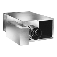
Each pressure input signal is routed
to the center averaging chamber
Equal concentric circular areas
Sizes 6 & 8: 3 Circles
Sizes 10 & 12: 4 Circles
Sizes 14 & 16: 5 Circles (shown)
Total pressure measured at the center
of each concentric circle for maximum
accuracy, as outlined in ASHRAE
Fundamentals Handbook.
Sizes 6 & 8: 12 Sensing Points
Sizes 10 & 12: 16 Sensing Points
Sizes 14 & 16: 20 Sensing Points
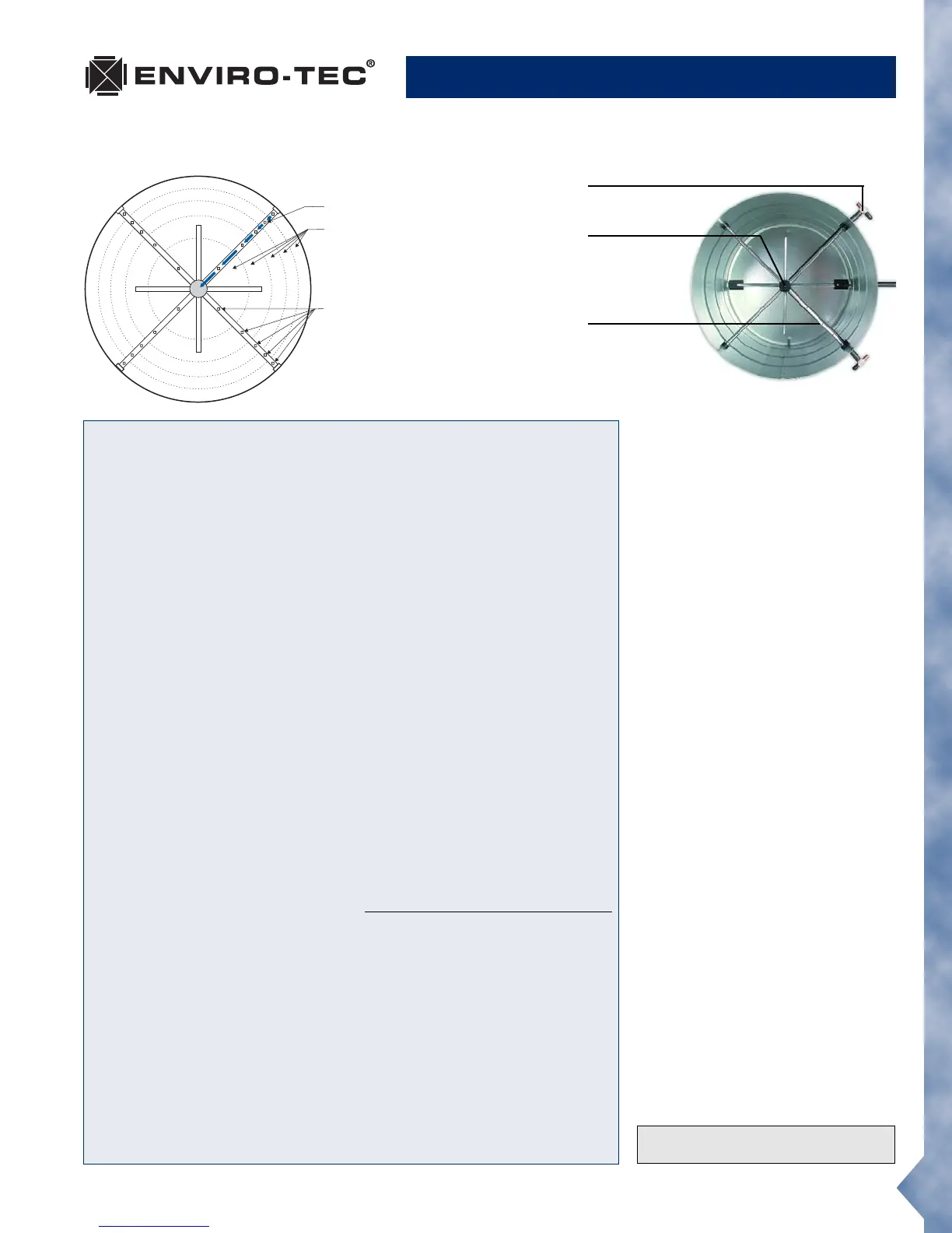
Brass field pressure
measuring tap
Airfoil shaped
averaging
chamber for low
pressure loss
and noise
Pressure output is
routed behind
probe to minimize
pressure loss
and noise
Accurate and Energy-Saving Airflow Control
With The Patented FlowStar™ Sensor
Many VAV terminals waste ener-
gy due to an inferior airflow
sensor design that requires the
minimum CFM setpoint to be
much higher than the IAQ cal-
culation requirement. This is
common with interior spaces
that will be effected year round.
These inferior VAV terminals waste
energy in several ways. First, the
primary air fan (e.g. AHU) supplies
more CFM than the building
requires. The higher minimum
CFM setpoint overcools the zone
with VAV terminals without inte-
gral heat. To maintain thermal
comfort a building engineer would
need to change the minimum set-
point to zero CFM compromising
indoor air quality. Inferior VAV
terminals with integral heat pro-
vide adequate comfort in the
space but waste significant ener-
gy as energy is consumed to
mechanically cool the primary
air only to have more energy
consumed to heat the cooled
primary air. Significant energy sav-
ings is obtained with proper
sizing and by making sure
approved VAV terminals are capa-
ble of controlling at low CFM
setpoints, providing the mini-
mum ventilation requirement.
Currently, most DDC controllers
have a minimum differential pres-
sure limitation between 0.015" and
0.05" w.g. The major DDC man-
ufacturers can control down to
0.015" w.g. An airflow sensor that
does not amplify, e.g., a Pitot tube,
requires about 490 FPM to devel-
op 0.015" w.g. differential
pressure. The FlowStar develops
0.015" w.g. pressure with only 290
FPM on a size 6 terminal and less
than 325 FPM for a size 16. Con-
sequently, VAV terminals utilizing
a non-amplifying type sensor
could have minimum CFM's that
are well over 50% higher than an
ENVIRO-TEC terminal. Many air-
flow sensors provide some degree
of amplification simply due to the
decrease in free area of the inlet
from large area of the sensor.
These VAV terminals still require
minimum CFM's up to 30% high-
er than an ENVIRO-TEC terminal,
have higher sound levels, and
higher pressure drop requiring
additional energy consumption at
the primary air fan.
A VAV system designed with
ENVIRO-TEC terminals con-
sumes significantly less energy
than a comparable system with
competitor's terminals. The
FlowStar airflow sensor reduces
energy consumption by allowing
lower zone minimum CFM set-
points, greatly reducing
or eliminating “reheat”, and by
imposing less resistance on the
primary air fan.
The ENVIRO-TEC
®
air valve features the Flow-
Star™ airflow sensor which has brought new
meaning to airflow control accuracy. The
multi-axis design utilizes between 12 and
20 sensing points that sample total
pressure at center points within equal
concentric cross- sectional areas, effectively
traversing the air stream in two planes. Each
distinct pressure reading is averaged with-
in the center chamber before exiting the
sensor to the controlling device.
This sensor adds a new dimension to
signal amplification. Most differential
pressure sensors provide a signal between
.5 and 2 times the equivalent velocity
pressure signal. The FlowStar™ provides
a differential pressure signal that is 2.5 to
3 times the equivalent velocity pressure
signal. This amplified signal allows more
accurate and stable airflow control at low
airflow capacities. Low airflow control is
critical for indoor air quality, reheat
minimization, and preventing over cool-
ing during light loads.
Unlike other sensors which use a large
probe surface area to achieve signal
amplification, the FlowStar™ utilizes an
unprecedented streamline design which
generates amplified signals unrivaled in the
industry. The streamlined design also
generates less pressure drop and noise.
The VAV schedule should specify the
minimum and maximum airflow setpoints,
maximum sound power levels, and
maximum air pressure loss for each terminal.
The specification for the VAV terminal must
detail the required performance of the
airflow sensor. For maximum building
occupant satisfaction, the VAV system
designer should specify the airflow sensor
as suggested in the Guide Specifications
of this catalog.
FlowStar™ Airflow Sensor
Patent #5,481,925
 Loading...