APPLICATION AND SELECTION • CFR
©December, 2005 Environmental Technologies, Inc. • CFR Catalog
7
Achieving acceptable sound levels
in the zone begins with a proper-
ly designed central fan system
which delivers relatively quiet air to
each zone.
Supply Duct Pressure. One primary
factor contributing to noisy systems
is high static pressure in the primary
air duct. This condition causes high-
er sound levels from the central fan
and also higher sound levels from
the terminal unit, as the primary air
valve closes to reduce the pressure.
This condition is compounded when
flexible duct is utilized at the ter-
minal inlet, which allows the central
fan noise and air valve noise to break
out into the ceiling cavity and then
enter the zone located below
the terminal. Ideally, the system
static pressure should be reduced
to the point where the terminal unit
installed on the duct run associat-
ed with the highest pressure drop
has the minimum required inlet pres-
sure to deliver the design airflow
to the zone. Many of today’s
HVAC systems experience 0.5" w.g.
pressure drop or less in the main
trunk. For systems that will have
substantially higher pressure
variances from one zone to anoth-
er, special attention should be paid
to the proper selection of air ter-
minal equipment.
To date, the most common approach
has been to select (size) all of the ter-
minals based on the worst case
(highest inlet static pressure) condi-
tion. Typically, this results in 80% (or
higher) of the terminal units being
oversized for their application. This
in turn results in much higher equip-
ment costs, but more importantly,
drastically reduced operating
efficiency of each unit. This conse-
quently decreases the ability to
provide comfort control in the zone.
In addition, the oversized terminals
cannot adequately control the min-
imum ventilation capacity required
in the heating mode.
A more prudent approach is to uti-
lize a pressure reducing device
upstream of the terminal unit on
those few zones closest to the
central fan. This device could sim-
ply be a manual quadrant type
damper if located well upstream of
the terminal inlet. In tight quarters,
perforated metal can be utilized as
a quiet means of reducing system
pressure. This approach allows all
of the terminal units to experience
a similar (lower) inlet pressure.
They can be selected in a consistent
manner at lower inlet pressure
conditions that will allow more
optimally sized units.
Inlet duct that is the same size as
the inlet collar and as straight as pos-
sible will achieve the best acoustical
performance. For critical applica-
tions, flexible duct should not be
utilized at the terminal inlet.
Zoning. On projects where inter-
nal lining of the downstream duct
is not permitted, special consider-
ations should be made to assure
acceptable noise levels will be
obtained. In these cases, a greater
number of smaller zones will help
in reducing sound levels. Where pos-
sible, the first diffuser takeoff
should be located after an elbow
or tee and a greater number of small
necked diffusers should be uti-
lized, rather than fewer large necked
diffusers.
The downstream ductwork should
be carefully designed and
installed to avoid noise
regeneration. Bull head tee
arrangements should be
located sufficiently down-
stream of the terminal
discharge to provide an
established flow pattern
downstream of the fan.
Place diffusers downstream
of the terminal after the
airflow has completely
developed.
Downstream splitter dampers can
cause noise problems if placed
too close to the terminal, or when
excessive air velocities exist. If tee
arrangements are employed,
volume dampers should be used in
each branch of the tee, and bal-
ancing dampers should be provided
at each diffuser tap. This arrange-
ment provides maximum flexibility
in quiet balancing of the system.
Casing radiated sound usually dic-
tates the overall room sound levels
directly below the terminal. Because
of this, special consideration should
be given to the location of these
terminals as well as to the size of
the zone. Larger zones should have
the terminal located over a corri-
dor or open plan office space and
not over a small confined private
office. Fan powered terminals
should never be installed over
small occupied spaces where the
wall partitions extend from slab-to-
slab (i.e. fire walls or privacy walls).
Fan Terminal Isolation. Model CFR
fan terminals are equipped with suf-
ficient internal vibration dampening
means to prevent the need for addi-
tional external isolation. Flexible
duct connectors at the unit dis-
charge typically do more harm
than good. The sagging membrane
causes higher air velocities and
turbulence, which translates into
noise. Furthermore, the discharge
noise breaks out of this fitting
more than with a hard sheet metal
fitting.
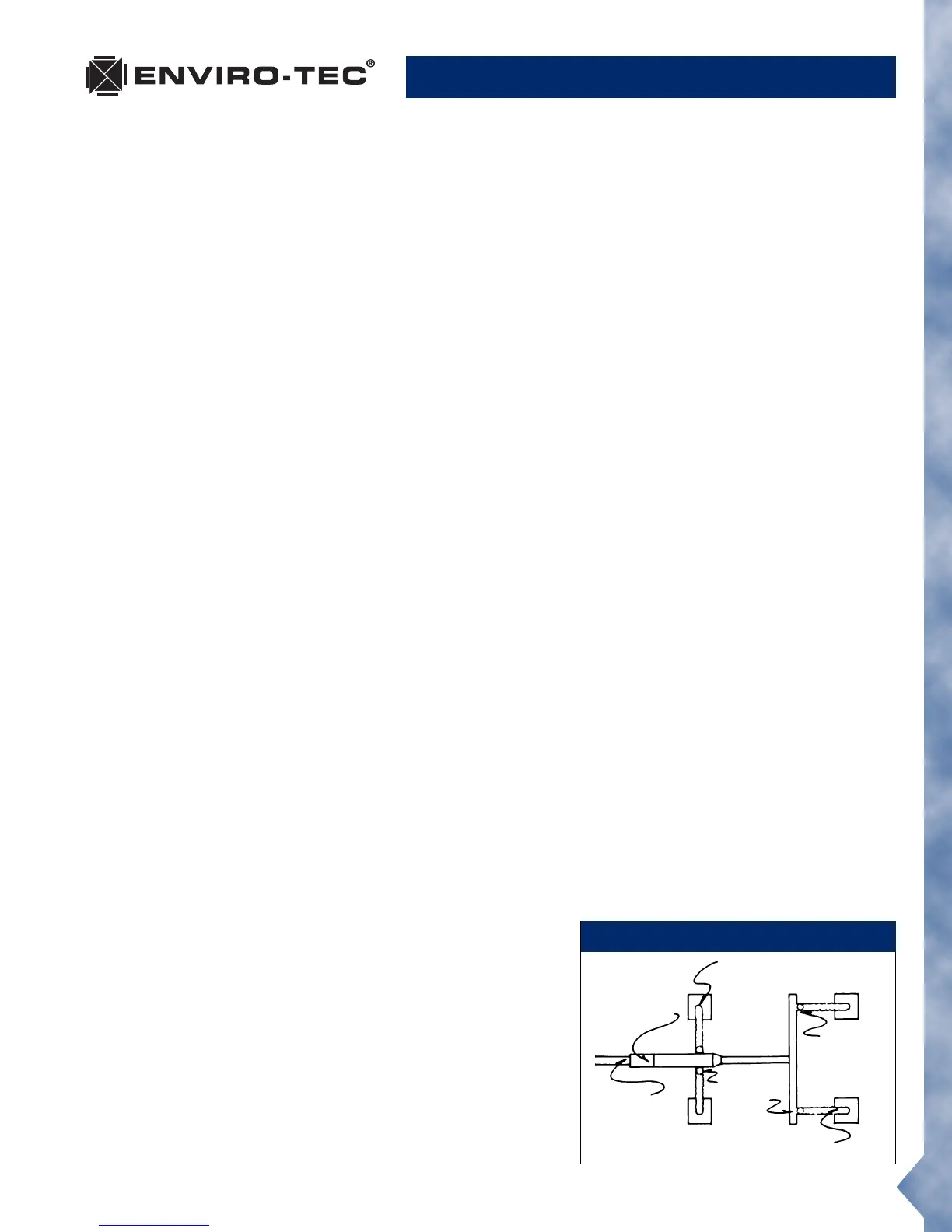
IDEAL DUCT DESIGN
Small Necked Diffusers
High Quality
VAV Terminal
with Low
Sound Levels
Minimum
Required
Inlet Static
Pressure
Multiple
Branch
Take-Offs
Damper
Located at
Take-Off
Short Length of
Non-Metallic Flexible Duct
 Loading...