CC
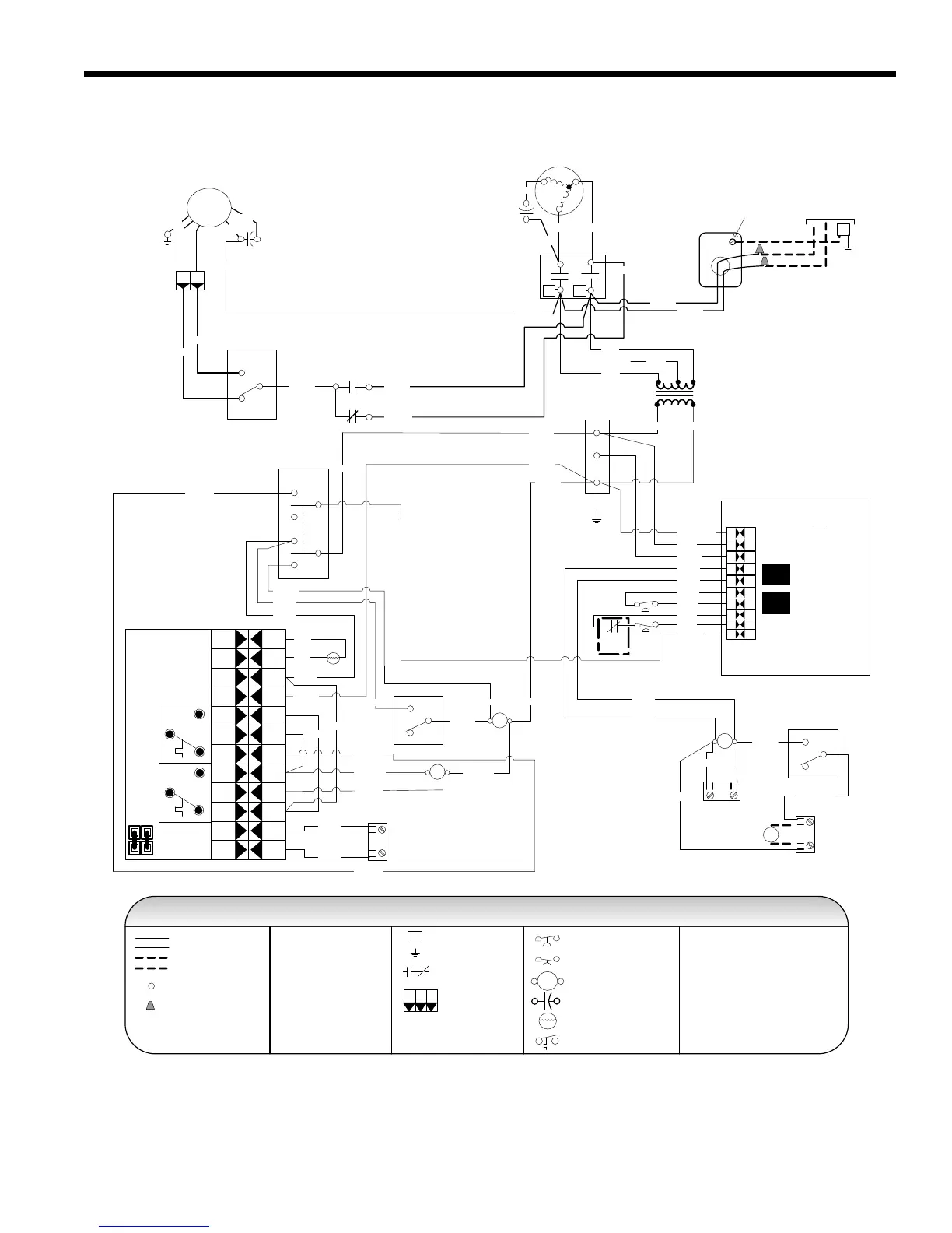
CCM – with Electronic Stat
Cap
Brn
Wht
Grn
PSC
Fan
Motor
Factory low voltage wiring
Temperature Switch
Factory line voltage wiring
Quick connect terminal
Wire nut
Notes:
1. Switch Red and Blue wires for 208 volt
operation
Field low voltage wiring
Field line voltage wiring
LP
HP
Handi - Box
Ground
Lug
HL
Cycled
Continuous
CC
T2
T1
Compressor
C
R
S
Tan (33)
Red Blk
Blue
L1
L2
High
Low
Auto
Fan
6
1
3
2
4
5
COMPRESSOR
CONTROL MODULE
TEST
PIN
HP H P CC CG L O R CLP LPY
HP H P CC CG L O R CLP LPY
Transformer
24V
Blue
230V
265V
Red
208V
Black
Yellow Black/White
Black/White (1)
Red (2)
Brown (3)
Black (6)
Black (7)
Blue (8)
Blue (9)
Ther
mistor
Electronic THERMOSTAT
T1
T3
B Cool
A Heat
T2
T4
T6
T5
SHUT
DOWN
24 V
AC
IN
PUT
T6
T4
T5
T2
T1
T3
Overide
Shut down
J1
Black
Violet (5)
Violet (4)
Yellow (13)
Yellow (10)
White (20)
Orange (14) Orange (21)
Black (29)
Red (30)
Black
Black (12)
White (18)
Red (11)
Red (19)
Red (17)
24 V A ccess or y
24VAC
S hutdown
Red (15)
Red (16)
NOTE 1
T
ST
CC - Compressor Contactor
HP - High Pressure Switch
LP - Low Pressure Switch
RV - Reversing Valve Coil
ST - Entering Air Temperature Sensor
RB - Blower Relay
Black
Black
Red (11)
Black (12)
Red (17)
Red (19)
Black (25)
White (28)
Black (31)
Red (32)
Brown (26)
RB
4
2
5
Red
RV
DT
ON
OFF
Damper Sw
Damper
Motor
D
Fan Mode Sw
Blk/Wht (24)
Blk/Wht (23)
Black (22)
White (18 )
Blue (T6)
NOTE 2
2. Terminal C of 24 V PB is used as “L”
output for Brown wire 3 for Lockout.
31
RB
Violet (4)
Blue/Wht (36)
Blue/Wht (35)
White (34)
Green (00)
FS
Yellow (13)
Not Used
Violet (5)
Yellow (13)
Yellow (10)
Legend
Console Unit – Wiring Schematic 208-230-265/60/1
6/10/08
Black (22)
White (28)
Black (27)
Brown (26)
DT - Damper Terminal Block
PB - Power Block
PB
1
2
3
Field wire lug
Earth Ground
Relay Contacts -
N.O., N.C.
Polarized connector
1
3
2
P
Switch - High Pressure
Switch - Low Pressure
Relay coil
Capacitor
Thermistor
HP
LP
T
L1
NOTE 3
3. Optional field installed freeze sensing
device.
FS - Freeze Sensing Device
G
Unit
Power Supply
208-230/60/1 or
265-277/60/1
 Loading...