10
Hot insertion tool�
CAUTION
The tip of the insertion tool can become hot and sharp when
used� Touching it can lead to burns and cuts�
• Never touch a hot or sharp insertion tool�
• Wait until the insertion tool has cooled down before carrying out
maintenance work�
Note: Never cool a hot insertion tool in water, it can result in brit
-
tleness and early failure�
Fitting the drill steel
Whenever fitting the drill steel the following instructions must be
observed:
Fitting and removing the tool
Before fitting the working tool
• Check that the tool shank is of the correct size and length for the
chuck used�
• The shank must be clean and the tool must be in good condition�
• The suitable quenching hardness of the shank is HRC48-53�
Harder end face will cause piston damaged and breakage of the
end face of the piston� If the shank face is too soft, it will be easily
deformed by the piston, which will result in difficulty in removing
the working tool�
• Shank end face shall be flat and perpendicular to the axis�
• Remove sharp edges from the shank's end face� Rough shank
surface will cause premature piston failure�
• Inspect the bits: Dull bits will slow down the drilling speed and
overstrain the drill mechanism� When changing bits make sure
that the new bit is the correct size to follow your previous bore�
• Before drilling check that the flushing hole in the working tool is
not blocked�
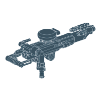
Fitting the working tool
1� Push the retainer outwards in the direction of the arrow (see
picture below), until the front portion of the retainer is able to ac-
commodate the working tool collar�
2� Insert the drill in the chuck�
3� When the drill bottoms, push back the retainer to lock it�
Removing the working tool
1� Push the retainer outwards in the direction of the arrow until the
working tool collar disengages from the front of the retainer�
2� Pull the working tool out�
3� Push back the retainer�
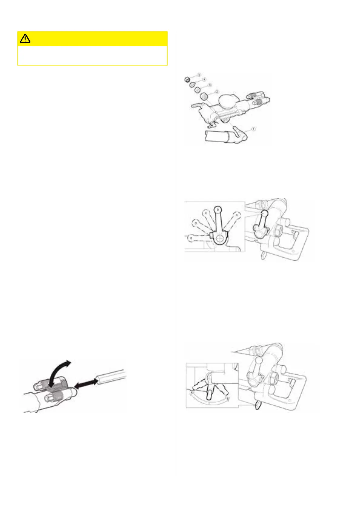
Attaching the pusher leg to the rock drill
• Mount the pusher leg (1), lock sleeve (2), rubber pad (3), washer
(4) and locking nut (5) in the order shown in the picture below�
• Turn the locking nut clockwise with a wrench until you hear a
"click"�
Controls
Throttle lever
The rock drill is equipped with a throttle lever for regulating both
the compressed air to the percussion mechanism and the flushing
water�
A� Extra blowing, water flushing off, impact and rotation off�
B� Stop position, air and water off
C� Low throttle, air to pusher leg, water flushing
D� Medium throttle
E� Full throttle
Feed control
Adjust the feed force by means of the feed control lever as fol-
lows:
A� Extra blowing, water flushing off, impact and rotation off�
B� Stop position, air and water off
Trigger
When the trigger (A) is pushed in, the feed force stops abruptly
and the setting on the feed control lever is overridden� The piston
rod in the pusher leg retracts automatically� This function is used
for example to adjust the height of the rock drill, when rigging up