Installation
Page 3-6
NOTES:
DIMM#2 & #3 shared same memory bus and DIMM#1 is dedicated for 2
nd
channel
memory bus.
For one DIMM memory configuration, the DIMM can be located on either of
DIMM#1 to DIMM#3 in 64-bit mode
In two DIMMs memory configuration, the DIMMs can be located on DIMM#2/#3
and DIMM#1 in 128-bit mode. And keeping these two DIMMs in same type and
same size are preferred.
In three DIMMs memory configuration, the DIMMs can be located on all DIMM
sockets in 128-bit mode.
Using non-compliant memory with higher bus speeds (overclocking) may severely
compromise the integrity of the system.
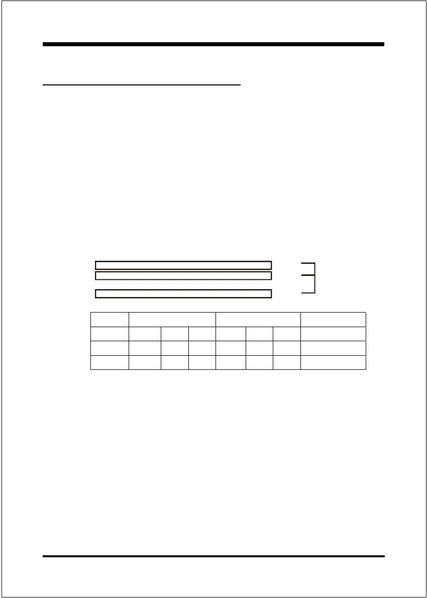
<Figure 6>
<Table 1>
DDR DIMM 2
DDR DIMM 1
DDR DIMM 3
Bank 0
DDR
Synchronous
DRAM
Bank 1
Section 3-3
System Memory Configuration
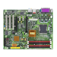
Memory Layout
The mainboard accommodates three PC1600/2100/2700/3200 184-pin DIMMs
(Dual In-line Memory Modules):
Supports up to 3.0GB of 200/266/333/400MHz DDR SDRAM
Supports up to 3 DDR DIMMs (refer to Table 1)
Supports 64/128/256/512Mb, 1Gb x8 & x16 DRAMs
Supports 128-bit dual channel memory architecture
Supports unbuffered non-ECC DIMMs
Supports configurations defined in the JEDEC DDR DIMM specification
Figure 6 and Table 1 show several possible memory configurations.
1 DIMM (64-bit) 2 DIMMs (128-bit) 3 DIMMs (128-bit)
DIMM#1 SS/DS SS/DS SS/DS SS/DS
DIMM#2 SS/DS SS/DS SS/DS SS/DS
DIMM#3 SS/DS SS/DS SS/DS SS/DS