IMPORTANT INSTALLATION WARNING
WARNING – TO REDUCE THE RISK OF SEVERE INJURY OR DEATH
1. READ AND FOLLOW ALL INSTALLATION INSTRUCTIONS.
2. Install only the proper length and material of gate arm. An improper gate
arm could cause severe injury. Have a qualified service person make repair
to gate.
3. Do not connect operator to source of power until instructed to do so.
INSTALLATION INSTRUCTIONS
1. Concrete foundations, not more than 6” above the driveway, with anchor bolts and
conduit should be finished per the applicable installation drawings.
2. Gate should be left on the wooden shipping platform, with cardboard left around it for
protection until it is ready to be mounted on foundation.
3. When ready to install, remove cardboard carton and machine bolts from the bottom of the
wooden platform.
4. Position gate with door facing away from driveway. Once the gate is in position, anchor it
down with ½” flat washers, ½” lock washers, and ½” hex nuts. Lubricate the bolts before
installation.
5. Open the top cover and install speed reducer breather plug.
6. Connect interconnecting wires to the other parts in the system by referring to the field
wiring diagram (page 5). Be sure all power is OFF when hooking up L1 and Neut. All
electrical wiring must be connected exactly as indicated in the wiring diagrams.
7. Turn the circuit breaker in gate housing OFF. The gate is now ready to operate. Turn
power on at L1 and Neut.
8. Turn the circuit breaker on and check initial gate activation by operating the RAISE/LOWER
switch.
9. Make adjustments to the up and down limit switch cams as required. NOTE: DOWN limit
switch has the black wire and the UP limit switch has the red wire. ENSURE CIRCUIT
BREAKER IN GATE IS OFF WHILE MAKING LIMIT SWITCH ADJUSTMENTS. To adjust
the cams, loosen the allen set screws and rotate the cams to the desired setting. After the
adjustments have been made, turn the circuit breaker on and test the gate arm travel by
operating the RAISE/LOWER switch. Repeat adjustments if needed.
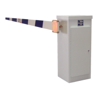
10. Gate arm may now be affixed to the gate arm flange by sliding the gate arm between the
flange and the break away flange cover and tightening down the four outside bolts.