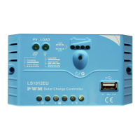
The LS-EU Series Solar Charge Controller is a device designed for solar power systems, offering efficient and reliable battery charging and load management. It utilizes Series PWM (Pulse Width Modulation) charging technology, which is known for increasing battery lifetime and improving overall solar system performance.
Function Description:
The primary function of the LS-EU series controller is to regulate the charging of a battery from a solar module and to manage the power supply to a DC load. It acts as an intermediary, ensuring that the battery is charged optimally and protected from various electrical faults, while also providing a stable power output for connected loads. The controller features LED indicators to intuitively display battery voltage status, charging status, and load status. It also includes a USB output for charging electronic equipment.
Important Technical Specifications:
- Nominal System Voltage:
- LS0512EU/LS1012EU: 12VDC
- LS1024EU/LS2024EU: 12/24VDC
- Maximum PV Input Voltage:
- LS0512EU/LS1012EU: 30V
- LS1024EU/LS2024EU: 50V
- Rated Charge/Discharge Current:
- LS0512EU: 5A
- LS1012EU/LS1024EU: 10A
- LS2024EU: 20A
- USB Output: 5VDC/1.2A (for all models)
- Max. Battery Voltage to Controller:
- LS0512EU/LS1012EU: 16V
- LS1024EU/LS2024EU: 32V
- Charge Circuit Voltage Drop: ≤0.26V (for all models)
- Discharge Circuit Voltage Drop: ≤0.15V (for all models)
- Self-consumption: ≤6mA (for all models)
- Temperature Compensation Coefficient (TEMPCO): -5mV/°C/2V (reference value, compensates equalize, boost, float, and low voltage disconnect voltage)
- Environmental Parameters:
- Working Temperature: -35°C ~ +55°C
- Storage Temperature: -35°C ~ +80°C
- Humidity: <95% N.C.
- Enclosure: IP30
- Mechanical Parameters (Dimensions - Overall, Mounting, and Weight):
- LS0512EU:
- Overall: 109.7(4.32)x65.5(2.58)x20.8(0.82)mm(inches)
- Mounting: 100.9(3.97)mm(inches)
- Terminal: 2.5mm²
- Weight: 95g
- LS1012EU:
- Overall: 120.3(4.74)x67(2.64)x21.8(0.86)mm(inches)
- Mounting: 111.5(4.39)mm(inches)
- Terminal: 4mm²
- Weight: 103g
- LS1024EU:
- Overall: 120.3(4.74)x67(2.64)x21.8(0.86)mm(inches)
- Mounting: 111.5(4.39)mm(inches)
- Terminal: 4mm²
- Weight: 102g
- LS2024EU:
- Overall: 148(5.83)x85.6(3.37)x34.8(1.37)mm(inches)
- Mounting: 138(5.43)mm(inches)
- Terminal: 6mm²
- Weight: Not specified in table, but implied to be similar to other models.
Usage Features:
- Battery Type Compatibility: Designed for use with Gel, Sealed, or Flooded batteries. The controller allows for selection of the battery type (Sealed lead acid, Gel, or Flooded) through a setting operation, ensuring appropriate charging parameters.
- LED Indicators: Provides clear visual feedback on the system's status:
- Charging Status Indicator (LED1): Indicates normal charging (On) or overvoltage (Fast Flashing).
- Load Status Indicator (LED2): Indicates load ON (On), load OFF (Off), or overload (Slowly Flashing).
- Battery Status Indicators (LED1, LED2, LED3, LED4): These LEDs, in combination, indicate the battery voltage state, including under voltage and over discharged conditions.
- Load Work Mode Setting: A setting button allows users to control the load output (ON/OFF). The USB output is active only when the Load Work Mode is ON.
- Temperature Compensation: Automatically adjusts charging and discharging parameters based on ambient temperature, which helps to improve battery lifetime.
- Electronic Switch: Utilizes MOSFET as an electronic switch, eliminating the need for mechanical switches and enhancing reliability.
Maintenance Features:
- Protection Functions: The controller incorporates several electronic protection mechanisms to ensure system safety and longevity:
- Load Overload Protection: Disconnects the load with a short delay if the current exceeds 1.25 times the rated current. The overload must be cleared by reapplying power or pressing the setting button.
- Load Short Circuit Protection: Automatically protects against load wiring short-circuits (exceeding 2 times the rated current). After one automatic reconnect attempt, the fault must be cleared by reapplying power or pressing the setting button.
- Battery Reverse Polarity Protection: Fully protects against incorrect battery wiring without causing damage to the controller. Normal operation resumes once the wiring mistake is corrected.
- Damaged Local Temperature Sensor Protection: If the temperature sensor is short-circuited or damaged, the controller will operate at a default temperature of 25°C to prevent battery damage from overcharging or over-discharging.
- High Voltage Transients Protection: The PV input is protected against high voltage transients. For lightning-prone areas, additional external suppression is recommended.
- Troubleshooting Guide: The manual provides a troubleshooting section to help users identify and resolve common issues based on LED indicator behavior, such as PV array disconnection, battery overvoltage, battery undervoltage, load overload, load short circuit, battery voltage lower than 6V, and solar module input voltage lower than battery voltage.
- No User Serviceable Parts: The controller is designed without user-serviceable parts, emphasizing that users should not attempt to disassemble or repair it.
- Installation Safety: Emphasizes the importance of reading all instructions, wearing eye protection, using insulated tools, ensuring sufficient ventilation, avoiding direct sunlight and water ingress, and confirming tight power connections to prevent excessive heating. External fuses/breakers are required for installation.