4
Step 1: Determination of Installation Location and Heat-dissipation Space
Determination of installation location: The controller shall be installed in a place with sufficient air flow
through the radiators of the controller and a minimum clearance of 150 mm from the upper and lower
edges of the controller to ensure natural thermal convection. Please see Figure 2-1: Mounting
CAUTION: If the controller is to be installed in an enclosed box, it is important to ensure
reliable heat dissipation through the box.
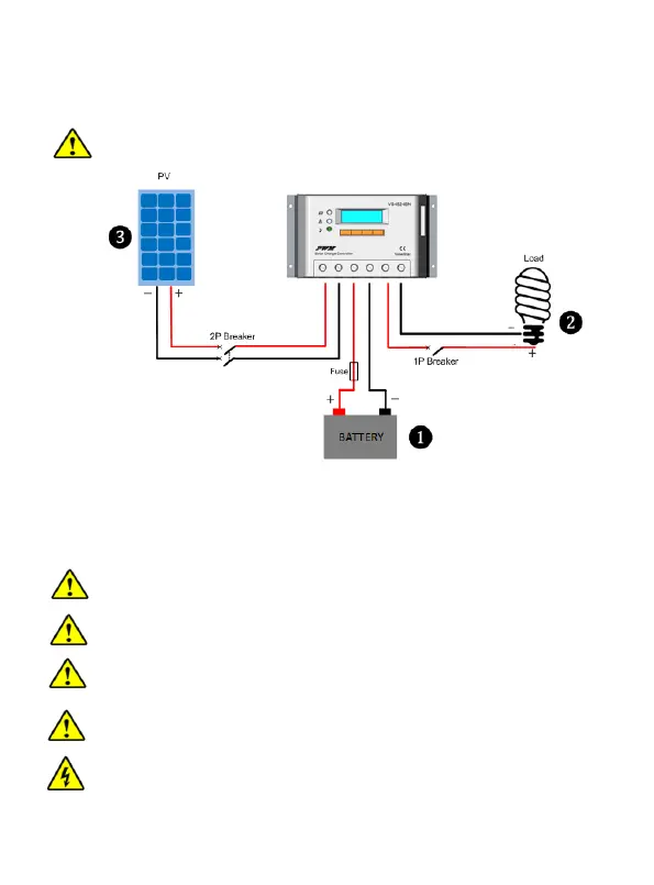
Step 2:Connect the system in the order of ❶battery ❷ load ❸PV array in accordance with Figure
2-2,”Schematic Wiring Diagram” and disconnect the system in the reverse order❸❷❶.
CAUTION: While wiring the controller do not close the circuit breaker or fuse and make sure that the
leads of "+" and "-" poles are connected correctly.
CAUTION: A fuse which current is 2 times the rated current of the controller.
NOTE: The controller is common negative one.
CAUTION: Don’t connect the loads with surge power exceeding the ratings.
CAUTION: Secure all wiring for mobile applications. Use cable clamps to prevent cables from
swaying. Unsecured cables create loose and resistive connections which may lead to
excessive heating and fire.
WARNING: Risk of explosion or fire! Never short circuit battery positive (+) and negative (-) or
cables.
Figure 2-2 Schematic of wiring
diagram
 Loading...