L200/L201/L100/L101 Revision A
Confidential
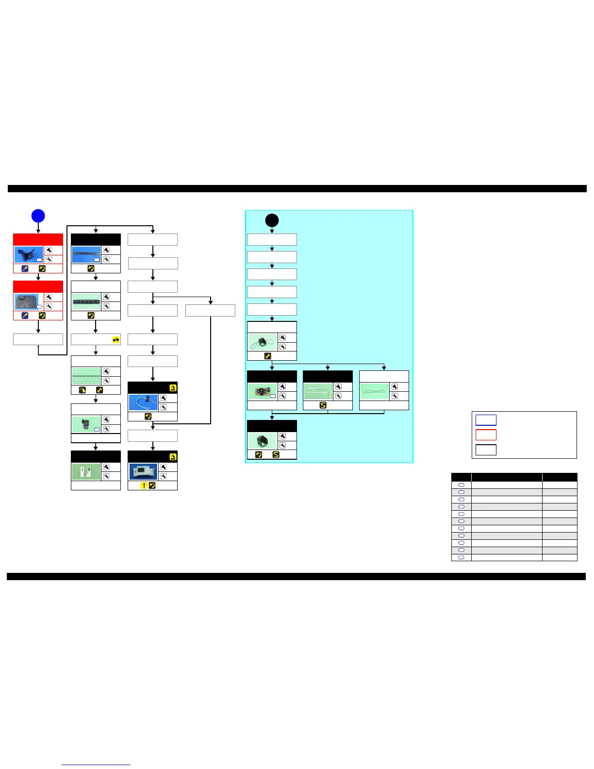
Disassembly/Assembly Disassembling/Assembling Flowchart 22
Flowchart 1-5. Disassembling Flowchart of Printer Mechanism Part (3)
Carriage
---
---
(p 25) (p 31)
1
Carriage Assy
---
---
(p 34)
PCB Encoder
2
---
---
S7
Timing Belt
---
---
---
Head FFC
---
---
(p 32)
CR Motor
Printhead
(p 20)
C
EJ Frame Assy
---
---
(p 27)
EJ Roller
---
---
(p 39) (p 34)
Waste Ink Pads
(for flushing)
---
---
---
Cover Flushing
1
---
---
S1
Ink Tube Guide
2nd
2
2
(p 27)
S2
EJ Roller Gear
Bottom Cover
Val v e Lev e r
Tube Valve Holder
Rear
Tube Valve Holder
Front
Valve Assy
---
2
(p 28)
Ink Supply Tank
Assy
---
7
(p 26)
Ink Tube Guide
1st
1
2
(p 30) (p 27)
S9
FFC Cover
Holder Contact
CR Front
Tube Pressing
Plate
Cap
L200/L201: (p 18)
L100/L101: (p 19)
Top Co v e r
Right Cover Left Cover
Screw type/torque list
Symbol Screw type Torque
C.B.P-TITE SCREW 3x8 5.0 ± 0.5 kgf·cm
C.B.P-TITE SCREW 3x10 5.0 ± 0.5 kgf·cm
C.B.S-TITE SCREW 3x5 7.5
± 0.5 kgf·cm
C.B.P-TITE SCREW 2.6x8 4.0 ± 0.25 kgf·cm
C.P.(P1) SCREW 2.6x3.5 3.5
± 0.25 kgf·cm
C.B.S-TITE SCREW 2x5 3.5 ± 0.25 kgf·cm
C.B.P-TITE SCREW 2x6 3.0
± 0.25 kgf·cm
C.F.B-TITE SCREW 2.6x6 3.0 ± 0.25 kgf·cm
C.B.P TITE SCREW 2.5x5 5.0 ~ 6.0 kgf·cm
C.B.P TITE SCREW 3x6 5.0 ~ 6.0 kgf·cm
C.B.P TITE SCREW 2.6x16 5.0 ~ 6.0 kgf·cm
S1
S2
S3
S4
S5
S6
S7
S8
S9
S10
S11
L200/L201 specific parts/unit
L100/L101 specific parts/unit
Common parts/unit
Ink Supply
Holder Assy
2
4
(p 30) (p 30)
S10