L200/L201/L100/L101 Revision A
Disassembly/Assembly Routing FFCs/cables 32
Confidential
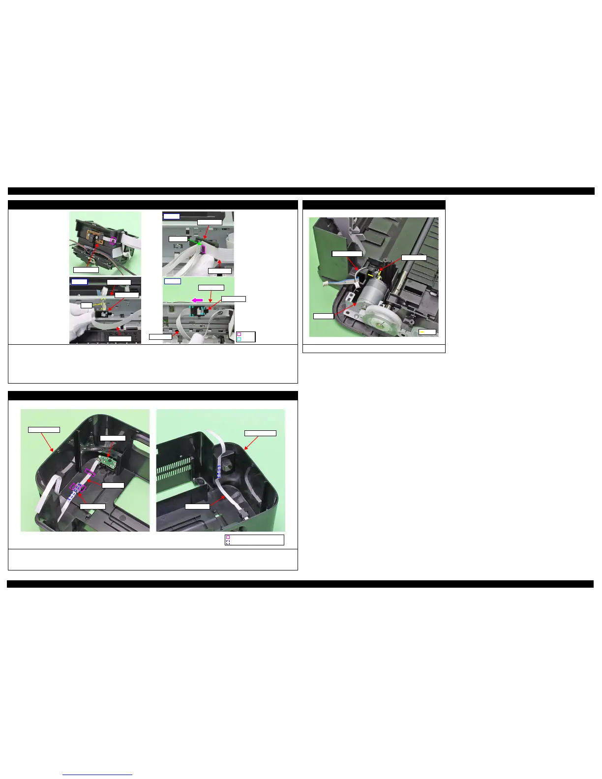
Head FFC
When installing the Head FFC to the Carriage, route the Head FFC through the rib (x1) on the rear of the Carriage, and connect the Head FFC to the CR
Encoder.
When installing the Head FFC to the Main Frame, route the Head FFC in the procedure below and connect it to the Main Board.
1. Align the fold line of the Head FFC with the rib (x1) of the Holder FFC, and route the FFC through the Holder FFC as shown in the figure above.
2. Route the Head FFC through the hole of the Main Frame.
3. Align the hooks (x4) of the Holder FFC with the holes (x4) on the Main Frame, and secure the Holder FFC to the Main Frame by sliding it to the 80-digit side.
Panel Board (L100/L101)
When routing the Panel FFC, follow the instructions below.
1. Route it through the Ferrite Core and the hook (x1).
2. Secure the FFC with double-sided tape (x2) to the Upper Housing, and then secure the Ferrite core with the hooks (x2).