RC90 Controller – Option Board Installation Procedure
RC90 Option Board Installation Rev. 2 1
RC90 Option Board Installation Procedure
■
Before performing any maintenance procedure, always make sure that the
main power of the Controller is turned OFF and that the high voltage charged
area is completely discharged. Performing any maintenance procedure
while the main power is ON or the high voltage charged area is not
discharged completely is extremely hazardous and may result in electric
shock and/or cause serious safety problems.
WARNING
■
When opening or closing the front side, make sure that the 200 V power
supply for the Controller is OFF. Performing procedure to the power supply
terminal block inside the Controller while the power supply is ON is extremely
hazardous and may result in electric shock and/or cause serious safety
problems.
- Be careful not to damage cables. Be sure not to drop any screws into the Controller.
- Installing the front cover using the wrong screws may result in a cable being damaged
and/or malfunction of the Controller.
C
Option Board
(1) Turn OFF the Controller.
(2) Unplug the power connector.
Option Board
Addition
(3) Remove the Top Panel. (Mounting screws ×10)
(4) Remove the clamp of the power supply cable.
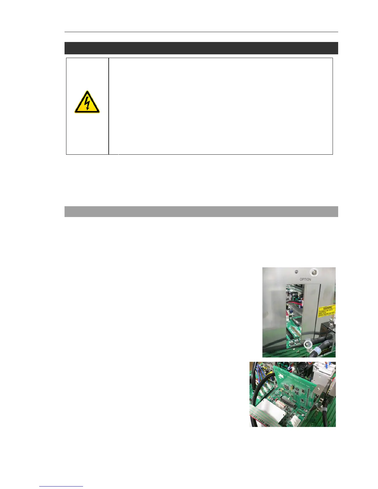
(5) Remove the screws of the Option Slot Panel
(×4).
When installing one Option Board:
Slide the panel as shown in the picture and
install the board with screws (×2).
When installing two Option Boards:
The Option Slop Panel is not necessary.
(6) Install the Option Board as shown in the
picture.
)
NOTE