RC90 Controller – Option Board Installation Procedure
2 RC90 Option Board Installation Rev. 2
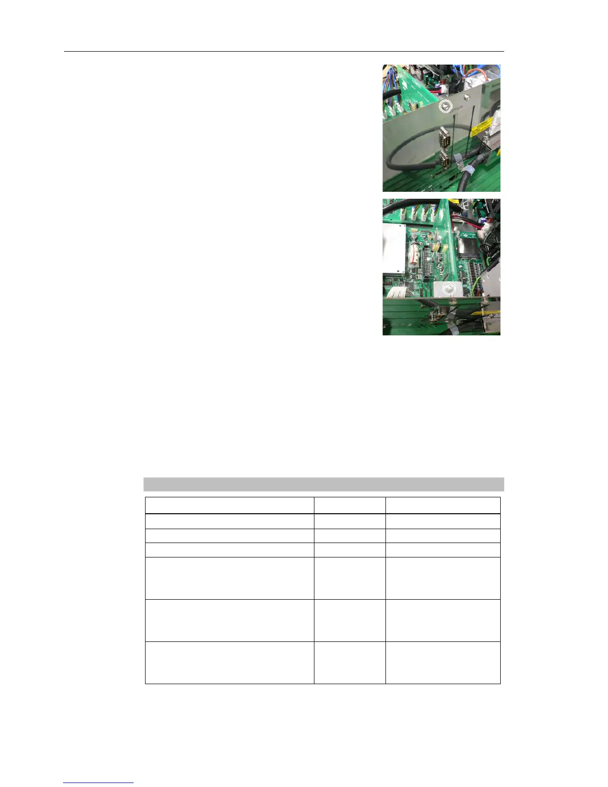
(7) Mount the attachment L-shaped plate with a
screw from the front side.
At this point, one screw for the Option Slot
Panel is left unused.
(8) Secure the L-shaped plate and Option Board
with the attachment screw.
(9) Mount the clamp of the power cable.
(10) Mount the Top Panel. (Mounting screws ×10)
(11) Plug in the power connector. Turn ON the Controller and make sure that the
Controller starts properly without any vibration or abnormal noise.
- Do not forget to configure your option after Turn ON according to your requirements.
For details see manual EPSON RC+ 5.0 User's Guide.
Available Option Boards
Part Name Code Note
Expansion I/O Board (PNP/Source type) R12B040302 24 In- / 16 Outputs
Expansion I/O Board (NPN/Sink type) R12B040303 24 In- / 16 Outputs
RS-232C Board R12B040726 2 Channels
DeviceNet Board R12B040727
DeviceNet module is
mounted on the Fieldbus
Board.
PROFIBUS Board R12B040729
Profibus module is
mounted on the Fieldbus
Board.
CC-Link Board R12B040730
CC-Link module is
mounted on the Fieldbus
Board.
)
NOTE