Epson Stylus SX230 series / SX235W series / SX430W series / SX440W series Revision B
Disassembly/Reassembly Routing FFCs/cables 40
Confidential
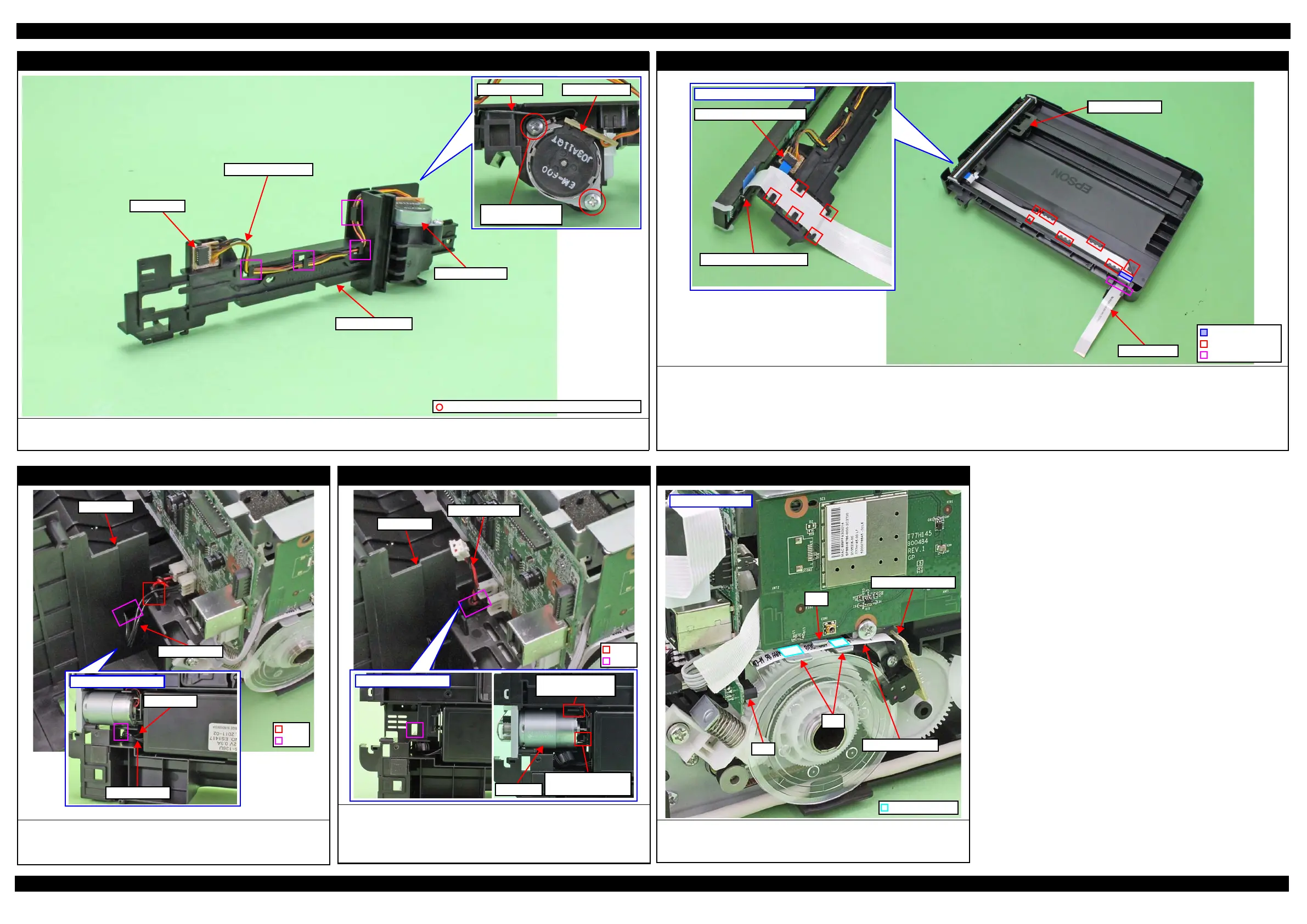
Scanner Motor
Route the Scanner Motor cable through the hooks (x4) of the Scanner Motor as shown above.
Secure the grounding wire of the Relay Board and the Scanner Motor together with the screw as show above.
Relay Board
Scanner Motor cable
C.B.P-TITE SCREW 3x10 F/ZN-3C (5 ± 1 kgf·cm)
Grounding wire
Scanner Motor
Screw it with
grounding terminal
Scanner Motor
Scanner Carriage
Scanner FFC
Route the Scanner FFC as follows.
1. Insert the Scanner FFC through the hole of the Scanner Housing Lower in the direction shown above, and then secure the FFC with double-sided tape on
position shown in the figure above.
2. Route the FFC through the ribs (x7) of the Scanner Housing Lower taking care not to damage the FFC.
3. Route the FFC through the ribs (x5) on the bottom of the Scanner Carriage taking care not to damage the FFC.
4. Connect the Scanner FFC to the Relay Board and CIS Module as shown above.
Bottom of Scanner Carriage
Connector of Relay Board
Connector of CIS Module
Hole
Scanner FFC
Scanner Carriage
Rib
Double-sided tape
PS Unit
Pull out the PS Unit cable from the hole of the Frame Base first, and then
route it through the rib of the Frame Base.
Put the ferrite core into the position shown in the figure above.
Bottom of Frame Base
PS Unit cable
Ferrite core
PF Motor
Route the PF Motor cable as follows.
1. Pull out the PF Motor cable from the hole of the Frame Base.
2. Install the PF Motor, and secure the PF Motor cable (black) with the rib of
the Frame Base, and then route it through the rib of the Frame Base.
PF Motor
Route PF Motor
cable through rib.
Secure PF Motor
cable (black) with rib.
PF Encoder Sensor
Route the PF Encoder FFC through the ribs (x2) of the Main Frame and
connect it to the connector (CN7) on the Main Board, and then secure it with
double-sided tape (x2) on the positions shown in the figure above.
PF Encoder FFC
CN7
Left side of printer
Ribs
Rib
PF Encoder Sensor
Double Side Tape
 Loading...