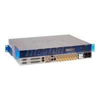
The ERECA Stage Racer is an optical transmission stage box designed for robust and versatile signal management in professional audio and video environments. It serves as a 1RU rack solution, ideal for base station fitment, and can also be integrated into 4 to 5 RU fly cases for field applications, allowing ample space for connections. A more compact, rugged box integration for 4-channel stage racers is available by special order.
Function Description:
The Stage Racer facilitates the optical transmission of a wide array of signals, including HD/SD/3G video, analog audio, digital audio (AES/MADI), serial data (RS232/422/485), Ethernet, and General Purpose Input/Output (GPIO). It acts as a central hub for converting and transmitting these diverse signals over fiber optic cables, ensuring high-quality and reliable communication between remote locations and a base station.
The device is designed for bidirectional signal flow, with many ports capable of both input and output, configurable via a web server interface. This flexibility allows the Stage Racer to adapt to various production needs, from live events to broadcast setups.
Important Technical Specifications:
Optical:
- Dynamic range: 10 dB for 12 channels (11.5 dB/8Ch, 13 dB/4Ch) pathological signal.
- Connector: NEUTRIK OpticalCon DUO or LEMO 3K (EDW / FXW). Other options like Quad, LC, SC/APC, ST/PC are available.
- Redundant path (Optional): Double optical transmission with automatic optical path selection.
- Optical losses (Redundant path): 1.8 dB per link for optical switching.
Video SD/HD:
- Number, connector: 4 to 12 channels on BNC (Each channel is direction configurable).
- Direction setting: Internal Web Server.
- Impedance: 75 Ω.
- Standard: SDI, ASI, HD, 3G.
- Reclocker: Bypass available for SDTI or MADI compatibility.
- Amplitude: Input: cable equalization (140 m Belden 1694A for 3G), Output: 800 mV pp.
- Return loss: Better than 15 dB for 0 to 1500 MHz and better than 10 dB for 1500 to 3000 MHz.
- Caution: Avoid connecting 50 Ohm plugs to BNC video ports as it can damage the socket central pin, leading to costly repairs.
Analog Video / GL:
- Number, connector: 1 Bidirectional, 2 BNC.
- Standard: PAL, SECAM, NTSC, Tri-level (Bi / Tri level auto sense).
- Impedance: 75 Ω.
- Bandwidth: > 5.8 MHz at +/- 0.2 dB.
- Differential Gain/ Phase: < 1%, < 1°.
- Group delay: < 10 ns.
- SNR: > 67 dB (CCIR567).
Analog Audio:
- Number, connector: 16 bidirectional channels. For rugged box: 4 on XLR / 4 on one SUB D 25 socket; for 1U rack: all on SUB D 37.
- Impedance: Input: 10 KΩ differential (non floating), Output: 20 Ω differential (non floating).
- Amplitude: +4 dBm nominal (saturation at + 18 dBm).
- Bandwidth: 50 Hz to 15 KHz at +/- 0.5dB, (20 Hz to 20 KHz at -3dB).
- Distortion: 0.05% at 1Khz +18 dBm.
- Signal to noise ratio: 90dB, "A" weighted.
- Mic input, Gain (Optional): Microphone input gain block on 8 of the 16 channels, from 10 to 60 dB, Bypass and Tunable by 3 dB steps, through internal Web Server.
- Phantom power (Optional): 48 volts switchable, through internal Web Server, Source Impedance 6.8 KΩ.
- Caution: After switching off phantom power, 48V will remain present for a significant time on inputs due to capacitor discharge.
Digital Audio:
- Number, connector: 4 AES bidirectional (Riedel panel compatible) OR 1 MADI (AES10) + 2 AES bidirectional (Riedel panel compatible).
- Bitrate: Up to 48 KHz AES audio / 125 MBs full bandwidth for MADI, clock phase conservative.
- Impedance / Connector: 75 Ω, BNC.
- Setting: Internal Web Server.
- Note 1 (AES): For internal 2-4 wire converter, source/terminal impedance of connected machine must be 75 Ohms.
- Note 2 (AES): Bidirectional function requires accurate AES activity LED display and avoids signal loop if port impedance is not 75 ohms. FPGA seeks AES3 audio XYZ preamble at 48 KHz to light the LED and enable transmission.
- MADI transmission: MADI clock information is transmitted along the MADI signal, with precise regeneration at the receiving side. MADI output VCXO capture range is +/- 100 ppm. More MADI signals can be passed through Video channels by selecting the right channel direction and bypassing the reclocker.
Data:
- Number, connector: 2 bidirectional channels, 1 RJ 45 socket per channel.
- Protocols: RS485, RS422, RS232.
- Data rate: 0 to 230 Kbd/s.
- Setting: Internal Web Server.
- RS422/485 Pinout (RJ45): Pin 1: GND (Shield), Pin 2: GP IN, Pin 3: RX RS 422 – (Stage racer electrical OUTPUT), Pin 4: TX RS 422 – (Stage racer electrical INPUT), Pin 5: TX RS 422 + (Stage racer electrical INPUT), Pin 6: RX RS 422 + (Stage racer electrical OUTPUT), Pin 7: GP OUT, Pin 8: GP OUT. For half-duplex RS485, bridge pins 3 with 4 and 5 with 6.
- RS232 Pinout (RJ45): Pin 1: GND (Ground ref/Shield), Pin 2: GP IN, Pin 3: RX RS 232 (Stage racer electrical OUTPUT), Pin 4: TX RS 232 – (Stage racer electrical INPUT). Pins 5 and 6 are not connected.
- Extra RS422 (Optional): 12 bidirectional channels via two D-SUB 25 female sockets (6 channels each). Datarate is about 25Kbds. Each differential input is not 120 Ohms loaded internally; a small SFR16 resistor can be added for impedance matching.
Ethernet:
- Number, connector: 2 channels on VLAN (802.1.ab), RJ45 Socket.
- Protocols: 10, 100 or 1000 mb/s, Full or Half-duplex (Auto), MDI or MDI-X (Auto).
- VLANs: Separated with 802.3AD VLANs, adding a service tag on input frames and removing it on transmitted frames. Networked audio (Ethersound / Dante / Ravenna) is correctly transmitted.
- Note: The admin web server is accessible on PORT 1.
GPIO:
- Number, connector: 8 bidirectional GPIO contacts. 6 on D-SUB plus 1 GPIO along each DATA RJ45 connector.
- Output: Relay (dry contact). 'Common' - 'Normally Open' terminals for each relay. Floating dry contact relays with 50 Volts AC/DC and 0.25 A switching capacity.
- Input: Floating on the D-SUB, Input pin grounding on RJ45. Opto-coupler protected. Automatic 5mA current limitation with 5 to 24 Volts input.
- Power: 12 volts output, 100mA resettable fuse (polyswitch) common to GPIN and GPOUT socket.
Powering:
- Consumption: 20 Watts per side.
- Low voltage source: 8 to 20 VDC, XLR 4 pins connector, protected by 5*20 mm standard internal fuse.
- Mains source: From 90 to 260 VAC / 47 to 63 Hz. Dual supplies in the 1U rack.
Mechanical:
- Rugged model: Die cast strong aluminum case, size 335 x 235 x 111mm excluding connectors and handles.
- Rack model: 1 RU 19" rack, depth 300mm excluding connectors.
- Cooling: Internal fan / (Case walls acting as Heat sink / No dust entry guarantee for the RUGGED).
- Operating Temp range: From -20 to + 60°C. (Avoiding direct sun exposition).
Usage Features:
- Web Server Configuration: Most settings, including signal direction, serial protocol, and audio gain, are managed through an internal web server, providing a user-friendly interface for setup and monitoring.
- LED Indicators: The front panel features LEDs to indicate signal activity for each channel, as well as technical alarms (power supply, temperature, fiber alarm). This information is also reported on the web browser "signal status" page.
- Optional Connectors: The front face provides access to optional SC/APC terminals for OpticalCon Quad connections, LED status indicators for optional signal transmission (e.g., 12 RS422 TX/RX activity), and D-SUB 25 female sockets for optional serial signals.
- Dual Power Supply: The 1U rack model supports dual power supplies (90-260 VAC) for redundancy and reliability.
- Remote Powering (Optional): The device can be remotely powered via LEMO 3K, providing 12VDC, 30W on XLR 4. This feature supports powering a rugged STAGE RACER box alone or with a 30W camera load over significant distances (e.g., 950m with AWG16 SMPTE cable).
Maintenance Features:
- Fuses: The front panel includes fuses for PSU1 and PSU2 (2 Amperes Slow Blow 5*20mm fuse), allowing for easy replacement in case of power issues.
- Default Settings Reset: If the IP address is lost, pressing the S1 switch on the front face for 5 seconds will revert the unit to its default settings.
- Supervision: All signal presence and alarms are reported through the web server, enabling remote monitoring and troubleshooting.
- Internal Fan: The unit is equipped with an internal fan for cooling, with case walls also acting as a heat sink.
- Technical Manual: Further detailed information is available in the Stage Racer Technical Manual, which can be requested from ERECA.