Do you have a question about the Erica Synths BASSLINE and is the answer not in the manual?
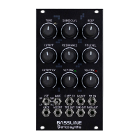
Detailed explanations for each of the 19 controls on the Bassline module's front panel.
Instructions for soldering horizontal resistors, diodes, ferrite beads, and IC sockets on PCBs.
Guide to soldering IC sockets and capacitors, including resettable fuses on the Controls board.
Solder potentiometers, switches, jacks, and transistors on the Controls board and resistors on Main board.
Solder transistors and opamps on the Main board, paying attention to polarity of electrolytic capacitors.
Install trimpots and pinheaders for jumpers, and insert ICs onto the circuit boards.
Solder male connectors onto the Main board at a 90° angle to the PCB.
Solder the PSU cable socket and two electrolytic capacitors onto the Controls board.
Connect the Controls PCB and Main PCB together and solder the female socket.
Secure the 11mm spacer with an M3x6 screw and insert LEDs without soldering.
Attach the front panel, solder LEDs, fix PCBs with screws, and install potentiometer knobs.
Connect PSU, set initial controls, and tune the VCO using a keyboard/MIDI-CV interface.
Adjust VCF cutoff and resonance, and fine-tune frequency scaling using specific trimpots.
Addresses suboscillator malfunctioning due to pulse wave peaks, offering component modification.
| Oscillators | 1 VCO |
|---|---|
| MIDI | MIDI In |
| Keyboard | No |
| Type | Analog Synthesizer |
| Waveforms | Sawtooth, Square |
| CV Inputs | Gate |
| Audio Output | 1/4" TS |
| Power Supply | 12V DC |