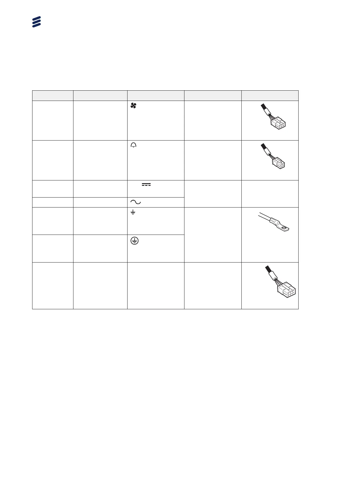
Table 20 Support Connection Interfaces, Dual Radio
Position Description Marking Connector Types Cable Types
A Fan unit PCB connector
B External alarm PCB connector
C −48 V DC power
supply
Screw terminal
block
–
C AC power supply
D Grounding
(With DC power
supply)
M8 bolt
D Grounding
(With AC power
supply)
E Power Output DC PCB connector
5.1.1 Position A, Fan Unit Interface
The fan unit provides cooling to the Radio Core.
5.1.2
Position B, External Alarm Interface
Two external alarms can be connected to the radio external alarm port.
5.1.3
Position C, AC/−48 V DC Power Interface
Depending on the version of the product, the power supply for the radio can
be AC or DC.
Radio Description
36
180/1551-LZA 701 6001/1 Uen AC | 2017-11-08