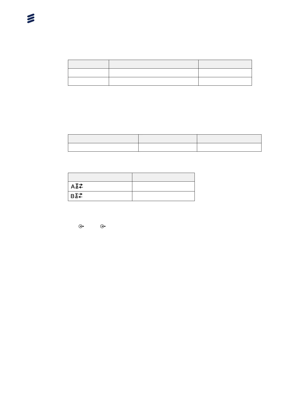
Position Description Marking
F TX monitor A TX MON A
G TX monitor B TX MON B
5.2.1 Position A and B, Antenna Interface
The antenna interfaces provide connections for the radio to the antennas. RF
cables connect the radio to the antenna.
Table 24 Radio Antenna Connection Interface Characteristics
Connector Type RF Cable Type Cable Connector Type
4.3-10, insert-receiver type 50 Ω coaxial 4.3-10 type
Table 25 Radio Antenna Cable Connectors
Radio Connectors Antenna Connectors
(Antenna A)
TX/RX
(Antenna B)
TX/RX
5.2.2 Position C and D, Interface for Optical Cable to Main Unit
The 1 and 2 interfaces provide connections to optical cables (with outer
diameter 4.5–5.5 mm, and complies with standard G657A2) for traffic and
timing signals between the radio and the main unit. A Small Form-Factor
Pluggable (SFP+) is used to connect the optical cable to the radio.
Note:
The radio uses SFP modules for optical transmission and optical radio
interfaces on Data 1 and Data 2.
Only SFP+ modules approved and supplied by Ericsson are to be used. These
modules fulfill the following:
•
Compliance with Class 1 laser product safety requirements defined in
standard IEC 60825-1
•
Certification according to general safety requirements defined in standard
IEC 60950-1
•
Functional and performance verified to comply with Radio System
specifications
Recommended SFP+ modules are obtained from the product packages for the
Radio System and the Main Remote Installation products. For more
information about SFP+ modules, refer to Spare Parts Catalog and Main-
Remote Installation Products Overview.
Radio Description
40
180/1551-LZA 701 6001/1 Uen AC | 2017-11-08