2.2.
VioletVioletBluBlue e TuTurqurquoisoiseeWhiteWhite
Alarm Alarm A A Alarm BAlarm B
Ge7635AGe7635A
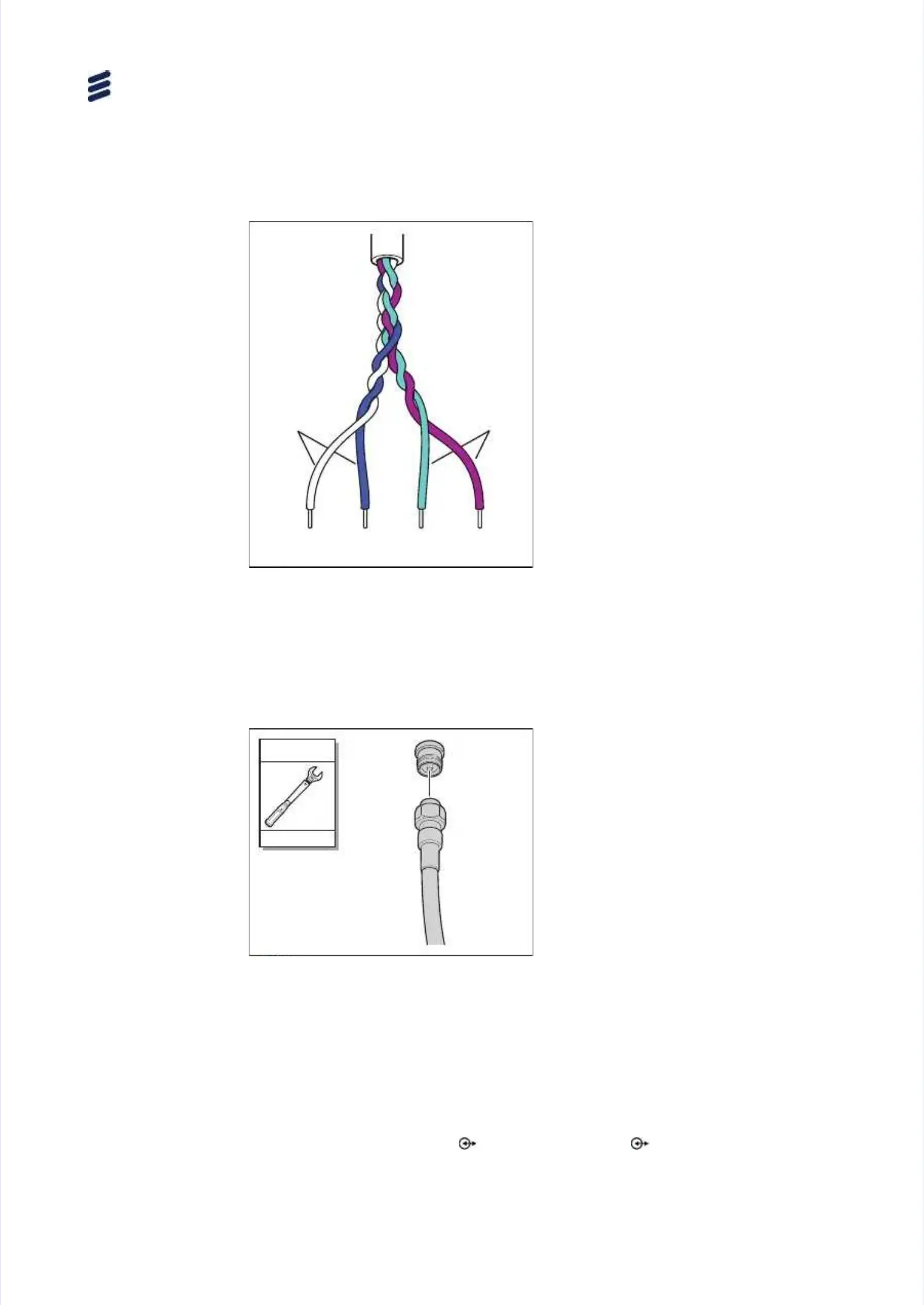
Connect the external alarm cableConnect the external alarm cable
to the external equipment usingto the external equipment using
the following cable data:the following cable data:
Alarm AAlarm A
•• White conductorWhite conductor
•• Blue conductorBlue conductor
Alarm BAlarm B
•• Turquoise conductorTurquoise conductor
•• Violet conductorViolet conductor
66..66..77 CCoonnnneecct t RRF F CCaabbllee
StepsSteps
To connect the RF cable:To connect the RF cable:
1.1.
Ge7786C
Ge7786C
5 Nm5 Nm
22 mm22 mm
Connect the RF cable.Connect the RF cable.
Note:Note: Make sure to use theMake sure to use the
correct cable type withcorrect cable type with
4.3-10 connector.4.3-10 connector.
Note:Note: If using a TMA, specificIf using a TMA, specific
configuration rules apply,configuration rules apply,
seesee Manage HardwareManage Hardware
EquipmentEquipment..
66..77 OOppttiioonnaal l AAccttiioonnss
The actions in this section are optional and can be performed if necessary.The actions in this section are optional and can be performed if necessary.
66..77..11 CCoonnnneecct t CCaassccaaddiinng g RRaaddiio o 2222119 9 aannd d RRaaddiio o 0022008 8 ((OOppttiioonnaall))
Radio 2219 and Radio 0208 can be cascaded. The Radio 2219 is thenRadio 2219 and Radio 0208 can be cascaded. The Radio 2219 is then
connected connected from from the the optical optical port port 2 2 to to the the optical optical port port 1 1 on on the the Radio Radio 0208.0208.
Install Radio
Install Radio
2626
67/67/15153131-L-LZA ZA 70701 61 600001/1/1 1 UeUen n JJ || 20201717-0-06-6-0606
 Loading...


