The ARES series of gate operators, manufactured by Erreka, are designed for the automation of swing gates. This quick installation and programming guide provides a summary of the complete manual, which contains essential safety warnings and detailed explanations. The full manual is available for download from the Erreka website.
Function Description:
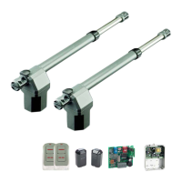
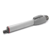
The ARES operators are electromechanical devices that automate the opening and closing of swing gates. They are suitable for both single and twin gate installations, offering robust and reliable operation. The system can be controlled via various inputs, including pushbuttons, key switches, and remote controls. Safety features such as photocells are integrated to prevent the gate from closing on obstacles. The operators are designed for both inward and outward opening gates, with specific assembly positions and dimensions provided to ensure optimal performance and opening angles.
Important Technical Specifications:
Electrical Connections:
The ARES operators can be connected to different control boards depending on the model and power requirements.
- For models except AE3324I and AE3324D: The VIVO-M101(M) switchboard is recommended for single operator installations, while the VIVO-M201(M) is recommended for twin operator installations.
- VIVO-M201: 230Vac/50Hz
- VIVO-M201M: 125Vac/60Hz
- Operator Connections (A1/A2):
- G1/G4: Open
- G2/G5: Close
- G3/G6: Common (COM), grey cable
- Capacitors: C1, C2
- Gate Status Indicators: DL4 (Gate opening), DL5 (Gate closing)
- Control Inputs: PUL1 (Close mini-pushbutton), PUL2 (Open mini-pushbutton)
- Earth Connection: T
- When PUL1 is pressed, DL5 lights up, and G2/G5 and G3/G6 connectors are activated.
- When PUL2 is pressed, DL4 lights up, and G1/G4 and G3/G6 connectors are activated.
- For models AE3324I and AE3324D: The VIVO-D201(M) switchboard is recommended.
- VIVO-D201: 230V, 50Hz
- VIVO-D201M: 125V, 60Hz
- Motor Cables: G1/G4 (Red cable for motor), G2/G5 (Blue cable for motor)
- Main Switch: SW1
Cable Specifications:
- Photocells (Tx/Rx): 2 x 0.5mm² or 4 x 0.5mm² (max. 30m)
- Flashing Light: 2 x 0.5mm² (max. 20m)
- Pushbutton or Key Switch: 2 x 0.5mm² (max. 25m)
- Operator (E): 4 x 1mm² (max. 20m)
- Main Power Supply (A): 3 x 1.5mm² (max. 30m)
Physical Dimensions and Opening Angles:
The assembly positions (A and B) determine the opening angle (C).
- Short Operator (Run: 300 mm):
- Inward Opening:
- A=140cm, B=140cm, C=95°
- A=120cm, B=160cm, C=120°
- Overall length (operator + gate arm): 920 mm
- Outward Opening:
- A=140cm, B=140cm, C=95°
- A=120cm, B=160cm, C=120°
- Overall length (operator + gate arm): 630 mm
- Long Operator (Run: 400 mm):
- Inward Opening:
- A=190cm, B=190cm, C=95°
- A=135cm, B=185cm, C=120°
- Overall length (operator + gate arm): 1.130 mm
- Outward Opening:
- A=190cm, B=190cm, C=95°
- A=135cm, B=185cm, C=120°
- Overall length (operator + gate arm): 730 mm
Limits on Use (Gate Weight vs. Length):
The maximum gate weight decreases as the leaf length increases.
- AE33IPL-AE33DPL, AE3324I-AE3324D:
- Max. 500 Kg for 1.7m leaf length.
- Max. 200 Kg for 2.5m leaf length.
- An electrolock is recommended for leaf lengths over 1.8m.
- BGRBI-BGRBD; BGRBIM-BGRBDM; BGRRI-BGRRD:
- Max. 700 Kg for 1.7m leaf length.
- Max. 250 Kg for 3m leaf length.
- BGRBIL-BGRBDL; BGRRIL-BGRRDL:
- Max. 700 Kg for 2.7m leaf length.
- Max. 250 Kg for 4m leaf length.
- These values are for orientation purposes; the actual performance may vary significantly based on the gate's form and wind conditions.
Usage Features:
- Manual Drive: The operator includes a mechanism for manual unlocking in case of power failure, allowing the gate to be opened or closed manually. It can then be relocked for motorized operation.
- Installation Flexibility: The supports should be positioned so that the operator forms a 1° angle with respect to the horizontal, with the gate support side remaining lower. This ensures proper operation and drainage.
- Programming (for AE3324I and AE3324D with VIVO-D201(M)):
- Number of Operators: Select using parameter C0 (C001 for one operator, C002 for two).
- Directions: Select using C1 (A1) and C2 (A2).
- Encoder/Limit Switches: Program for operation without encoder or limit switches (C700).
- ARES 24V Operator: Program 304.
- Thrust Adjustment: Adjust the thrust according to the gate's weight (parameter 86).
- Turning Direction Check: After power connection and activation, the gate performs a reset (display shows "-5"). It closes until it reaches the stopper, assigning this as the "gate closed" position. If it opens instead, the turning direction must be changed using C1 (A1) or C2 (A2).
Maintenance Features:
The manual implies that regular checks and adjustments are necessary for optimal performance, particularly regarding thrust settings and turning direction. While specific maintenance schedules are not detailed in this quick guide, the emphasis on correct installation and programming suggests that proper setup is key to minimizing future issues. The availability of a comprehensive manual indicates that detailed maintenance instructions are provided there.