FCU1 FCU2 FCUn
M2
Mn
M1
T1
Tn
T2
11
10
12
9.1
32
6
7
8
9.2
9
13
1.1
1.2
1.3
1.4
1.5
1
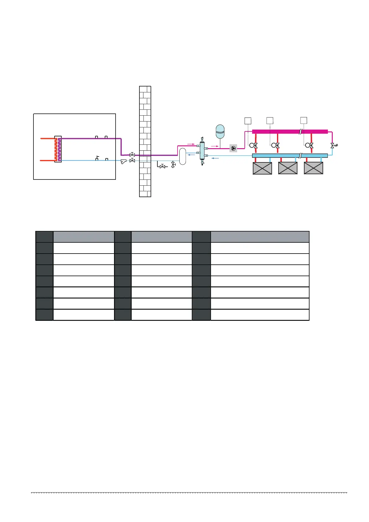
No. component No. component No. component
1 main unit 3 stop valve (field supply) 10 expansion vessel (field supply)
1.1 water side heat exchanger 6 drain valve (field supply) 11 P_o:outside circulation pump (field supply)
1.2 safety valve 7 fill valve (field supply) 12 collector (field supply)
1.3 manual air purge valve 8 buffer tank (field supply) 13 bypass valve (field supply)
1.4 water flow switch 9 balance tank (field supply
)
1.5 manual water drain valve 9.1 air purge valve M1...n motorized
valve (field supply)
2 y-shape filter 9.2 drain valve
7.2 Application 2
Space cooling and heating application without a room thermostat connected to the unit, but with heating/cooling thermostat controlling the fan
coil units. Cooling is provided through the fan coil units only.
Fig.7-2 diagram of application 2
Table 7-2
FCU 1...n fan coil units
T1…n room thermostat (field supply)
9