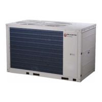
32
Detail information
No.
33
36
37
38 CN91:Three-phase protector output switch.(Protection code E8)
39
40
41
42
CN58:Fan realy driver port.
CN21:The thermostat switch.(not used)
CN8:Remote mode signal
CN8:Remote stop signal
43 CN8:Water flow switch signal
CN31:Temperature sensors input port
Th:System suction temperature sensor(10kΩ corresponds to 25ºC, B=4100).
Taf2:Water side antifreeze temperature sensor(10kΩ corresponds to 25ºC, B=4100).
Two:Unit water outlet temperature sensor(10kΩ corresponds to 25ºC, B=4100).
Twi:Unit water inlet temperature sensor(10kΩ corresponds to 25ºC, B=4100).
Tw:Total water outlet temperature sensor when several units are connected in parallel(10kΩ corresponds to 25ºC, B=4100).
CN3:Module 1 temperature sensor(10kΩ corresponds to 25ºC, B=4100).
34
CN10:Module 2 temperature sensor(10kΩ corresponds to 25ºC, B=4100).
35
CN15:Detection of current of the compressor system input port
INV1:Detection of current of the compressor A (protection code P4)
INV2:Detection of current of the compressor B (protection code P5)
CN69:Temperature sensors input port
Tp1:DC inverter compressor 1 discharge temperature sensor.(5kΩ corresponds to 90ºC, B=3950)
Tp2:DC inverter compressor 2 discharge temperature sensor.(5kΩ corresponds to 90ºC, B=3950)
Tz/7:coil final outlet temperature sensor.(10kΩ corresponds to 25ºC, B=4100)
Taf1:Water side antifreeze temperature.(10kΩ corresponds to 25ºC, B=4100)
CN19:Low voltage protection switch.(Protection code P1)
44
SW3:Up button
a) Select different menus when enter menu selection.
b) For sopt inspection in conditions.
SW4:Down button
a) Select different menus when enter menu selection.
b) For sopt inspection in conditions.
SW5:
Menu button
Press to enter menu selection, short press to return to the previous menu.
SW6:
OK button
Enter the submenu or confirm the function selected by short pressing.
Numerical code tube
1) In case of stand-by, the address of the module is displayed;
2) In case of normal operation, 10. is displayed (10 is followed by dot).
3) In case of fault or protection, fault code or protection code is displayed.
45
CN7:Inverter water pump signal.(0-10VDC output)
46
47
S5:Dip switch
S5-1/S5-2:
Low static pressure mode, OFF of S5-1 and S5-2 are enabled(factory default).
Middle static pressure mode, OFF of S5-1 and ON of S5-2 are enabled.
High static pressure mode, ON of S5-1 and either of S5-2 are enabled.
S5-3: No remote controll, OFF of S5-3 is enabled(factory default).
Remote controll, ON of S5-3 is enabled
CN7:Demand restricted port.(0-10VDC input)
48
30