Table 8-10
8.7.11.2 Table of diameter parameters of main inlet and outlet pipes
CAUTION
Please pay attention to the following items when installing multiple modules:
● Each module corresponds to an address code which cannot be repeated.
● Main water outlet temperature sensing bulb, target flow controller and auxiliary electric heater are under control of the main module.
● One wired controller and one target flow controller are required and connected on the main module.
● The unit can be started up through the wired controller only after all addresses are set and the aforementioned items are determined. The
wired controller is ≤500m away from the outdoor unit.
8.7.11 Installation of multi-module water system pipeline
Multi-module combination installation involves special design of the unit, so relevant explanation is given as follows.
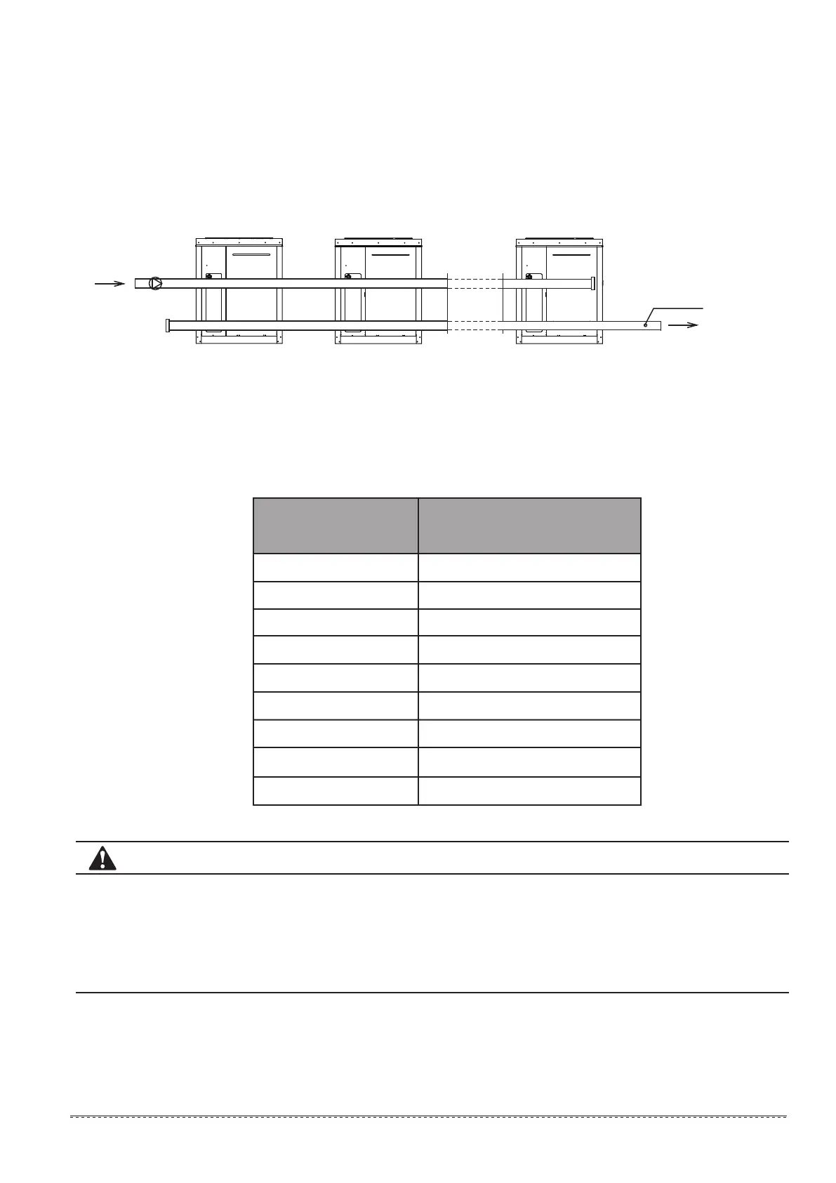
8.7.11.1 Installation mode of multi-module combination water system pipeline
Fig.8-33 installation of multi-module (less than 16 modules)
No.n module
No.(n-1) address
No.1 moduleNo.(n-1) module
No.(n-2) address No.0 address
Pump
Drill dead hole at the
position, and move the
total effluent temperature
sensor at No.0 address to
the position
15≤Q≤30
30<Q≤90
90<Q≤130
130<Q≤210
210<Q≤325
325<Q≤510
510<Q≤740
740<Q≤1300
1300<Q≤2080
DN40
DN50
DN65
DN80
DN100
DN125
DN150
DN200
DN250
Total inlet and outlet water
pipe inside nominal diameter
Cooling capacity
42