Phone Order
0466 909 653
Email Order
info@olct.co
Fax Order
07 3041 3232
Order Online
www.olct.co
+
AA
BATT
BATT
200
TEST
200k
V1000
Ω
Ω
8
4
3
+
+
+
+
AA
AA
AA
+
AA
AA
750 V
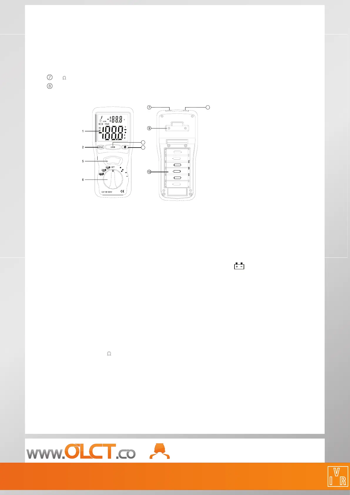
2. PARTS & CONTROLS
① Digital Display
② Data Hold Button
③
Lock Button
④ Backlight Button
⑤
Test Button
⑥
Rotary Function switch
⑦
V Ω Jack
⑧
COM input jack
⑨ Pothook
⑩
Battery Cover
3. BATTERY REPLACEMENT
3-1 How to connect test leads.
a). On M Ω Range: Connect the red test lead into the “
V
Ω
” terminal and the black lead into the “COM” terminal.
b) On 200
Ω
and ACV Range: Connect the red test lead into the “
V Ω
” terminal and the black lead into terminal
“COM”
3-2 Battery Check-UP & Replacement
a) When battery power is not sucient, LCD will display the low battery symbol. “ “ Replacement of 6 new
batteries, type 1.5V
size “AA” is required.
b). Place back the battery cover and four the screws.
3-3 Test leads check
Set the range select switch to the 200 Ω range. With the tip and alligator clip of the test leads connected. The
indicator should read 00.0
Ω
. When the leads are not connected the display will read innity indicated by “1”. This
will ensure that test lead are in good working condition.
4. INSULATION RESISTANCE MEASUREMENTS
a). Measurements at 200M Ω
/250V
This is the voltage used for the majority of insulation resistance tests on normal installation requirement. To
measure insulation resistance, press the test button to power on the tester. The LCD will display the insulation
resistance. Section VII indicated that subdivision of large installations might be necessary because of the large
number of parallel insulation resistance. In such a case, an installation may be divided into sections, each being
separately tested. Ea
ch section must have not less than fty outlets, an outlet being a switch, socket, lighting
point etc. A switched socket counts as one outlet. The minimum acceptable insulation resistance is 1M
Ω
.
For a large installation, the capacitance of the insulation will be high, and it will take longer for it to become
charged by the direct testing voltage. Care must be taken not to take a reading until there is a steady reading,
 Loading...