16
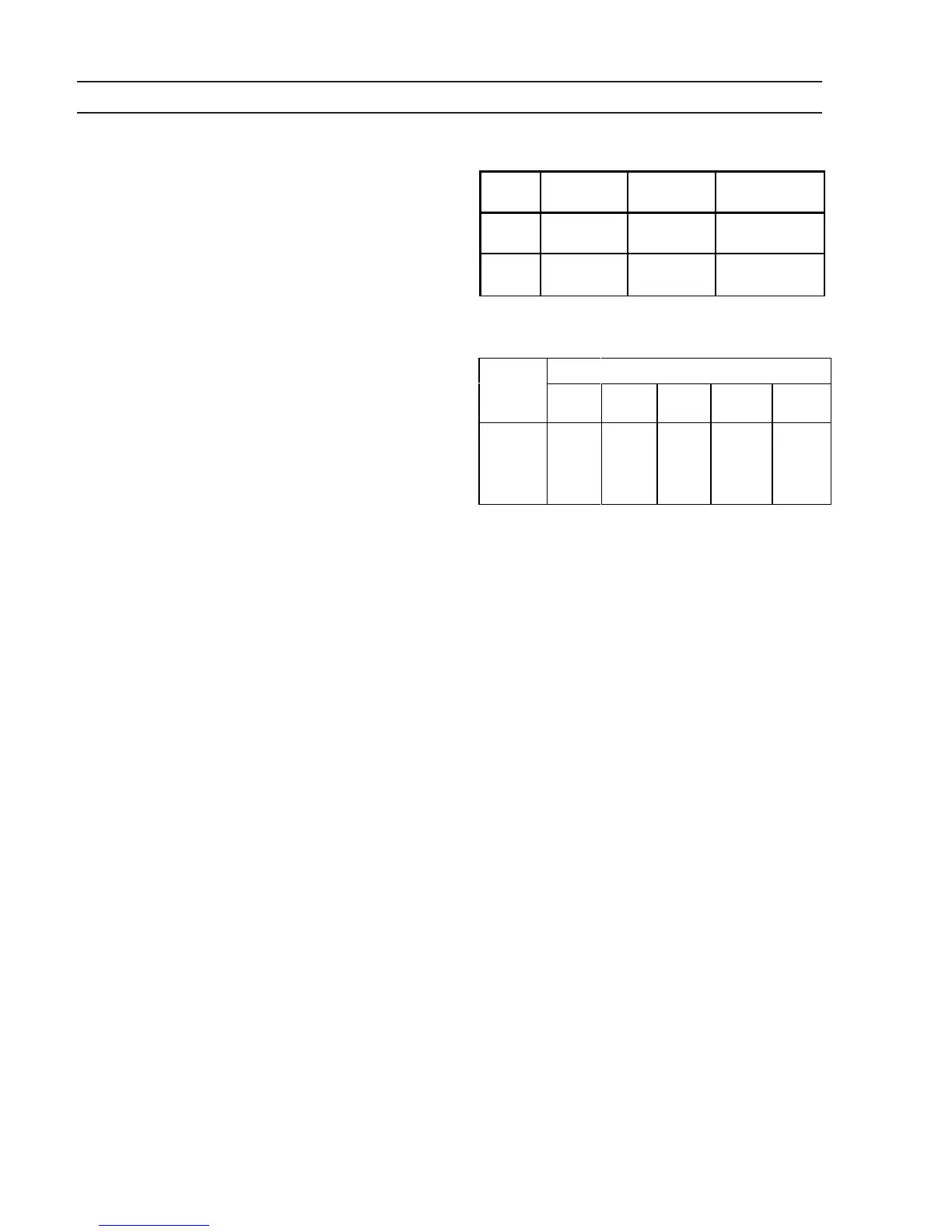
Table 2-2. Typical Output Connections
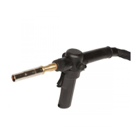
MIG Welding
(DCRP)
TIG Welding
(DCSP)
Stick Welding
(DCSP or DCRP)
Electrode
positive (+) negative (-)
positive (+) DCRP
negative (-) DCSP
Work negative (-) positive (+)
negative (-) DCRP
positive (+) DCSP
Table 2-3. Recommended Welding
Cable Sizes - AWG (mm
2
)
Welding
Current
Total Length (Feet) of Cable in Welding Circuit*
50
(13 m)
100
(25 m)
150
(38 m)
200
(51 m)
250
(64 m)
100
150
200
250
300
6 (16)**
4 (25)**
3 (30)**
2 (35)
1 (50)
4 (25)**
3 (30)**
1 (50)
1/0 (50)
2/0 (70)
3 (30)**
1 (50)
1/0 (50)
2/0 (70)
3/0 (95)
2 (35)
1/0 (50)
2/0 (70)
3/0 (95)
4/0 (120)
1 (50)
2/0 (70)
3/0 (95)
4/0 (120)
4/0 (120)
* Total cable length includes work and electrode cables. Cable size is based on direct
current, insulated copper conductors, 100% duty cycle, and a voltage drop of 4 or
less volts. The welding cable insulation must have a voltage rating that is high
enough to withstand the open circuit voltage of the machine.
** The supplied male output connectors will not accept anything smaller than #2 gauge
(35 mm ) cable.
as close together as possible to limit this resistance.
Make sure that the work cable (ground) is large enough,
kept as short as possible, properly insulated, securely
connected to the workpiece, and that all connections
are clean and tightly secured. If the work circuit includes
mechanical fixtures, ship structure, robot fixtures, etc.,
make sure that the circuit is secure and presents a low
resistance path to the flow of weld current. Also, the
power cable on a water-cooled torch is normally subject
to gradual deterioration and increasing resistance due
to corrosion which leads to the poor performance
described above. To assure good torch performance,
the water-cooled power cable should be replaced peri-
odically.
SECTION 2 INSTALLATION
 Loading...