Do you have a question about the ESAB Heliarc 353iAC/DC and is the answer not in the manual?
Outlines user obligations for safe operation and highlights critical safety cautions before use.
General safety overview, explanation of warning symbols (Danger, Warning, Caution), and their implications.
Guidelines for personal protective equipment, clothing, and measures to prevent fires and explosions.
Covers electrical shock hazards, magnetic fields, and protection against fumes and gases during operation.
Safe practices for cylinder handling, equipment maintenance, and additional safety references.
Details on warning symbol meanings, IP enclosure classes, and specific operational cautions.
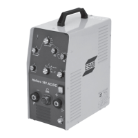
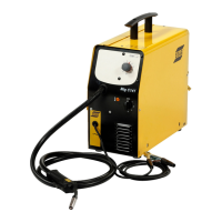
Introduction to the Heliarc AC/DC 281i, 283i, 353i welding power sources and their technology.
Detailed specifications including input voltage, output current, duty cycle, and dimensions for all models.
Guidance on minimizing radio frequency interference from welding operations.
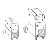
Instructions for assembling the trolley unit and mounting the power source onto it.
Connecting the unit to power supplies and the optional Water Cooler Unit (W.C.U.).
List of parts required for the assembly of the trolley unit, referring to Figure 4-1.
Step-by-step instructions for assembling the trolley unit, referencing Figure 4-2.
Procedure for attaching the welding power source to the assembled trolley, referencing Figure 4-3.
Steps for assembling the optional cooler and filling it with coolant, referencing Figure 4-5.
Connecting TIG torch, gas hose, work return lead, and optional remote controls.
Connecting electrode holder and work return lead for Stick (SMAW) welding.
Procedure for turning on the unit and understanding its initial standby mode and display.
Using remote controls, initiating TIG arcs (HF/Lift), and selecting AC/DC processes.
Configuring pulse parameters and setting up for MMA (Stick) welding.
Operating TIG welding using 2-torch and 4-torch switch modes with HF start.
Performing spot welding using the TIG process with a 2-torch switch and HF start.
Utilizing manual sequenced pulsing for TIG welding via torch switch operations.
Selecting tungsten types and preparing tips for optimal AC/DC TIG welding performance.
Using foot control for AC TIG and understanding tungsten electrode current limits.
Diagram and description of the main controls, displays, and indicator LEDs on the front panel.
Detailed explanation of specific front panel controls and their functions, numbered 1-24.
How to adjust parameters like frequency, pulse, balance, and gas flow using front panel encoders.
Adjusting Hot-Start, storing/recalling welding programs, and other advanced functions.
Table listing available welding modes and the functions supported within each mode.
Procedure for cycling through and selecting various welding modes (Stick, TIG 2T/4T/Spot/Dual).
Guide to setting up Stick (SMAW) mode, including Hot Start and Arc Force adjustments.
Setting up TIG 2-Stroke mode with a remote switch, adjusting down slope time.
Setting up TIG 2-Stroke mode with a foot control, adjusting down slope time.
Configuring TIG 4-Stroke mode, including slope times and final current level.
Setting up TIG Spot mode, including spot time and weld current level adjustments.
Turning on AC mode, adjusting frequency, and waveform balance for AC welding.
Setting the peak and background current levels for pulse welding operations.
Adjusting pulse frequency and duty cycle for AC and DC pulse welding.
Procedure for saving and retrieving custom welding parameter programs.
Setting HF start, slope times, and pre/post gas flow for various welding processes.
Importance of regular maintenance and safety precautions before performing any work.
Cleaning the power source air inlets and the welding torch for optimal performance.
Steps for cleaning the cooling unit, including disconnection and draining of coolant.
Procedure for safely filling the cooling unit with the specified coolant.
Details of the 36-month warranty coverage and common exclusions for the welding equipment.
| Brand | ESAB |
|---|---|
| Model | Heliarc 353iAC/DC |
| Category | Welding System |
| Language | English |