SCREWS (#42) MUST BE INSTALLED TO POLE AS DESCRIBED
IN STEP 3. FAILURE TO INSTALL SCREWS COULD RESULT IN
SERIOUS INJURY OR PROPERTY DAMAGE.
NOTE: Cordless drill required for screw installation. Do not over tighten screws causing screws to strip.
Once Screw heads touch pole, STOP! Overtightening will cause Pole to Warp and damage system.
NOTE: To install screws, it will be easier if you use a cordless drill with 5/16” socket (instead of Phillips head).
NOTE: Screws #42, used in step 3, are Self Drilling screws and can be installed without drilling pilot holes.
However, it will be easier to install screws if you drill 9/64” pilot holes in bottom pole. WEAR SAFETY
GLASSES if drilling holes.
DO NOT DUNK ON THIS UNIT .
DO NOT HANG FROM ANY PART OF THIS
UNIT , INCLUDING THE BACKBOARD, RIM,
SUPPORT BRACES OR NET.
4L-8152-01
WARNING
!
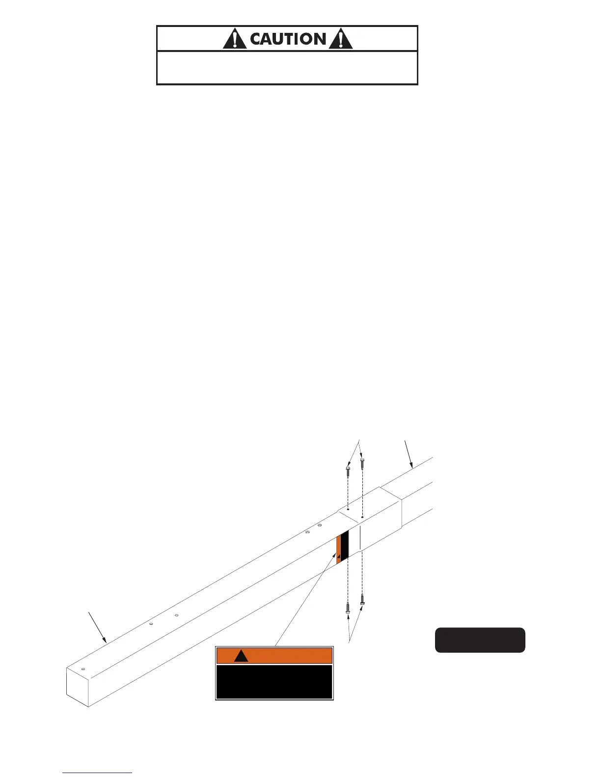
42
42
Figure 4
DO NOT DUNK ON THIS UNIT .
DO NOT HANG FROM ANY PART OF THIS
UNIT , INCLUDING THE BACKBOARD, RIM,
SUPPORT BRACES OR NET.
4L-8152-01
WARNING
!
NOTE: Self Drilling screws
(#42) are used. Holes are
only on outside Pole. User
must insert screws through
BOTH POLES.
3.
Once the Top pole is to the 6” Mark on the Warning Sticker, lay Pole Assembly on its side on two padded
saw horses. Insert a (#42) Screw into each 3/16” hole in top Pole, two on each side of the Post Assembly.
You will need someone to hold the Pole assembly while inserting screws. Screw must go through both Top
and Bottom (Inner) Poles. Make sure to not strip screws once they are all they way through. See Figure 4.
3
2
7