ASSEMBLY INSTRUCTIONS (Day 3)
9.
3
2
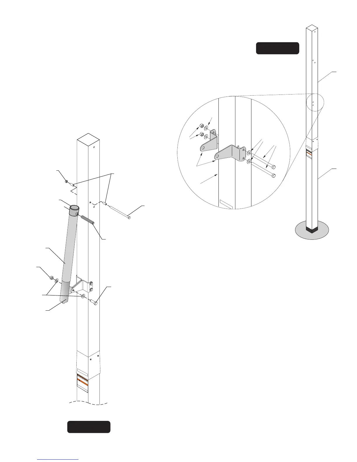
IMPORTANT! BE SURE CONCRETE HAS BEEN
ALLOWED TO CURE FOR AT LEAST 2 DAYS.
Figure 7
10.
11.
12.
Figure 8
Detail 2
Note: If necessary, use a rubber mallet to tap in
Pivot Tube (#14)
If not already pre-assembled, slide Plastic Actuator Sleeve
(#15) over Steel Actuator (#16) and place Actuator Cap
(#13) on top. Align holes in all 3 parts and slide Pivot Tube
(#14) through holes in Actuator Cap (#13), Plastic Actuator
Sleeve (#15) and Steel Actuator (#16) until equal amounts
stick out through both sides of actuator. See Figure 8.
7
10
4
14
15
16
19
20
21
13
FAILURE TO FULLY ENGAGE THE
BOTTOM OF THE UPPER POLE TO
THE 6” MARK ON THIS BOTTOM
POLE STICKER, COULD CAUSE
YOUR UNIT TO COLLAPSE AND MAY
RESULT IN SERIOUS INJURY OR
PROPERTY DAMAGE.
BACKSIDE
Bottom of upper
pole
must cover
the
above
orange portion of
this sticker
(6” mark).
W
ARNING
!
4L-8151-00
BACK SIDE
FAILURE TO FULLY ENGAGE THE
BOTTOM OF THE UPPER POLE TO
THE 6” MARK ON THIS BOTTOM
POLE STICKER, COULD CAUSE
YOUR UNIT TO COLLAPSE AND MAY
RESUL
T IN SERIOUS INJURY OR
PROPERTY DAMAGE.
BACKSIDE
Bottom of
upper pole
must cover
the
above
orange
portion of
this
sticker
(6” mark).
WARNING
!
4L-8151-00
BACK SIDE
10
Attach Post Ears (#30) to holes near the bottom of the Top Post (#3) using two
hex bolts (#25) four washers (#18) and two lock nuts (#4). Do not tighten
nuts (#4) completely until instructed to do so. See Figure 7 & Detail 2.
BACK SIDE
18
18
25
4
30
3
NOTE: Make sure (#14) Pivot Tube is
installed through all three parts:
1. Actuator Cap (#13)
2. Plastic Sleeve (#15)
3. Steel Actuator Tube (#16)
(#7) Bolt goes in
upper hole
Slide tab on Actuator (#16) between Post Ears #30 and
secure using one Bolt (#19), two Washers (#20) and one
Lock Nut (#21). Tighten Lock Nut (#21) snug but DO NOT
over tighten. See Figure 8. At this time also tighten nuts
(#4) from Step 9.
Secure two Stop Spacers (#10) to pole, as shown in Figure 8,
using one Hex Head Bolt (#7) and one Lock Nut (#4).
Tighten Lock Nut (#4) but DO NOT over tighten.