4.3. DESCRIPTION OF THE PARAMETERS.
5. GENERAL DESCRIPTION.
5.1. ADJUSTMENT.
4
8. MOUNTING.
9. INSTALLATION.
9
10. ADM ISSIONS.
6
2000 2050
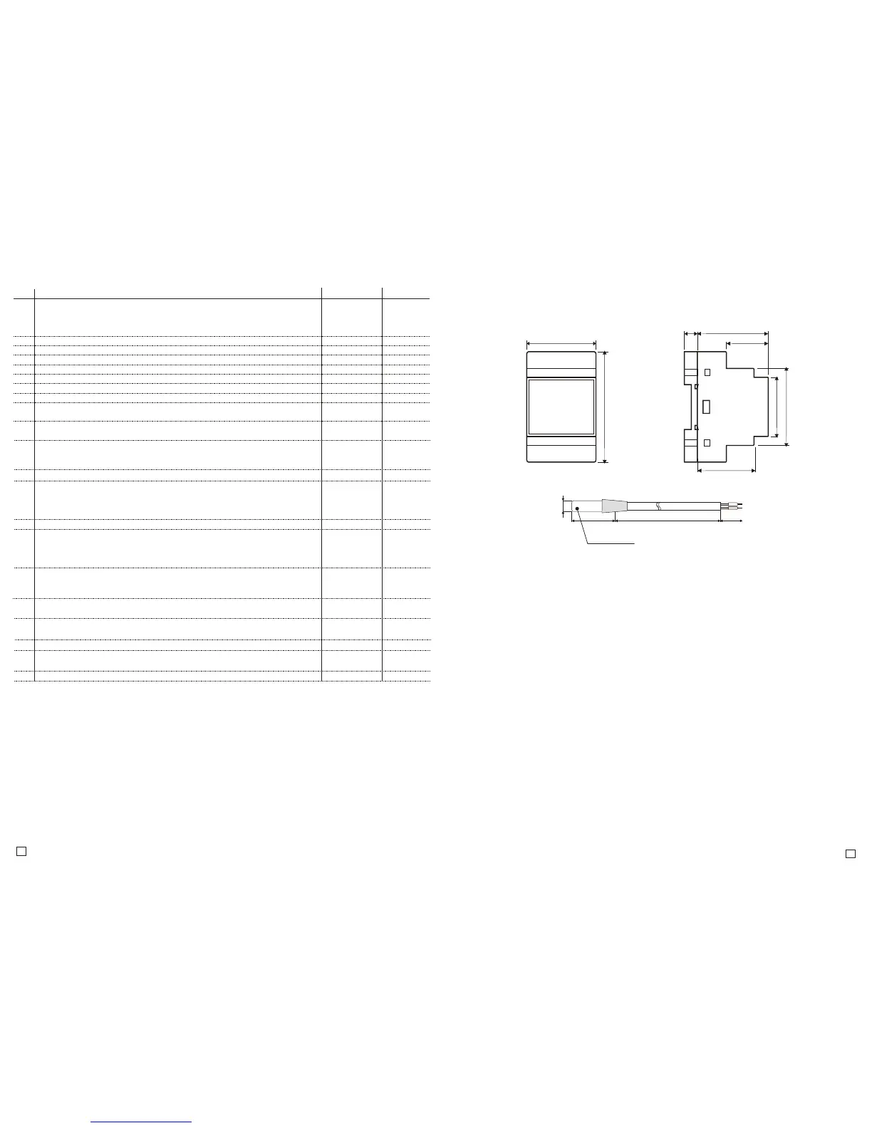
Protection class
IP67
50 (3 mod.)
89,5
14
51
32
45
67,2
35
Mounting on a DIN rail(TS35), 50cm width (3 modules).
Code: Default: Description:
F11 8.0°CValue of tempereture setting. Range of changes is limited by F14 and F13.
F12 0.5°CHysteresis (temperature control accuracy).
Range:
F14...F13
0.1...20.0°C
F13 150.0°CMaximum value possible to set by the user.
F14 Minimum value possible to set by the user.
-50.0...150.0°C
-20.0...+20.0°C
F19
0.0°C
Temperature sensor T1 calibration. This is the value of rescaling the T1
temperature sensor in relation to actually measured temperature.
F21
0.0min
Output1 minimum down time. It also means the delay time of switching
the output on after giving power supply. Parameter protects devices,
for example engine from too frequent switching in case of power failure.
0.0...10.0min
F29 COOL
Controlling output work mode: COOLING/HEATING
COOL/HEAT
F50
0
Digital input D1: 0 – unused; 1 – alarm when circuit 4-5 closed,
2 – alarm when circuit 4-5 closed with maintaince of alarm signalling,
3 – alarm when circuit 4-5 opened,
4 – alarm when circuit 4-5 opened with maintance of alarm signalling
0...4
F51 1Sound signaller (beep) active when temperature alarm: 0 – N0, 1 – YES
F52
0
The way of protection the system and the devices connected to the main
output when the temperature alarm occurs: 0 – main output off and locked
when an alarm, 1 – main output on and locked when the alarm,
2 – alarm does not affect the operation of the main output
0, 1
0, 1, 2
F80
OFF
Password to access the configuration menu.
OFF – password protection inactive, F80 = 0000 – no password
0000...9999
F83 0Display mode 0 - measurement from two sensors displayed alternately every
3 sec.; 1 - measurement from T1 sensor; 2 - measurement from T2 sensor
F98 -Reserved.
0, 1, 2
-
F99
-
Controller test. Disconnect output device to make the test!
Otherwise the system can crash.
-
End Exit the menu.
F57
0
Output2 contacts scheme: 0-contacts normally opened, closed when the
temperature alarm or when digital input activation; 1-contacts normally closed,
opened when the temperature alarm or when digital input activation
0, 1
F10
1
Controller work mode:
0 - normal (displays from the main sensor T1, auxiliary sensor T2 off)
1 - differential (display difference between auxiliary and main sensor (T2-T1)
2 - average (display average from two sensors: main and auxiliary (T1+T2/2)
0, 1, 2
-50.0°C
-50.0...150.0°C
F15 85°CHigh temperature alarm. F15=OFF – alarm off
F16 5.0°CLow temperature alarm. F16=OFF – alarm off
-50.0...150.0°C
-50.0...150.0°C
F17 0.1minThe delay of switching high and low temperature.
F18
0.0°C
Temperature sensor T2 calibration. This is the value of rescaling the T2
temperature sensor in relation to actually measured temperature.
0.1...99.9min
-20.0...+20.0°C
--
SC-20 is designed to control the heating and cooling system. A wide range of configuration
makes the controller perfect for use in typical arrangements, such as boiler or circulating pump
Control and complex, for example: solar collector or fireplace with water jacket control.
Adjustment is based on the measurement from one or two temperature sensors:
–when measuring from one sensor (F10=0) controller mainstains the set temperature switching on the
main output in ''heating'' or ''cooling'' mode with deviation (regulated hysteresis)
– when measuring from two sensors the user can select the operating mode of the controller:
–the output is activated based on the difference (F10=1) or average (F10=2) from two
temperature sensors.
In differential mode, the controller activates, e.g. Collector circulating pump after reaching an essential
difference between boiler's and collector's sensor. And in averaging mode, the controller operates as
an usual temperature controller except that the measured value is calculated from the arithmetic
average of readings from two temperature sensors, for example at the two ends of the pipeline or the
boiler.
Be aware of the conditions where the controller operates. Install in a place, where there is not
too high temperature and humidity and no condensation. Should be ventilated
in order to remove the heat.
ATTENTION!
It is not allowed to work with electric cables when the device is energized.
You should avoid crossing wires using short connections. We recommend securing the source
of controller power supply and temperature sensor input against electrical interference
Controller meets the requirements for immunity to electromagnetic interference in an
industrial environment according to the following standards:
Electromagnetic compatibility (EMC):
–EN-61000 part 6-4 – requirements for emissivity in an industrial environment
–EN-61000 part 6-2 – requirements for immunity in an industrial environment
It also meets the safety requirements according to standard:
–EN-61000 part 1 – safety requirements for eletrical devices
Controller meets the requirements of EU directives No. 72/23/EEC; 93/68/EEC; 89/336EEC.
 Loading...