Do you have a question about the Esco TC-11 and is the answer not in the manual?
Details on digital input signals and requirements for START, STOP, PAUSE, and RESET commands.
Specifies the relay output type, rating, and available operating modes.
Defines the configurable time ranges and methods for setting time units.
Covers time counting, measurement accuracy, and display characteristics.
Details power supply, protection class, operating, and storage conditions.
Specifies maximum resistive and inductive load capacities for the output.
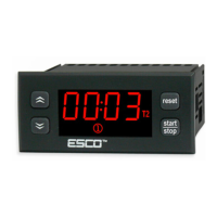
Identifies and describes the function of each front panel button and indicator.
Step-by-step instructions for configuring the T1 time value.
Guide for configuring the T2 time value, used in specific modes.
Procedure to enter the parameter menu and navigate through settings.
Details on how to access the menu when password protection is enabled.
Description of parameters related to timer operation and range selection.
Description of parameters related to button functions, buzzer, and software version.
Timer operates for T1 time, then turns output off and activates beeper.
Timer counts down T1 time, then turns output on and activates beeper.
Timer alternates output ON for T1 and OFF for T2 cyclically.
Timer alternates output OFF for T1 and ON for T2 cyclically.
Timer counts down T2, then output ON for T1 with beeper.
Timer counts down T1, then output ON for T2 with beeper.
How to use START, PAUZA/STOP, and RESET buttons for control.
Using digital inputs D1 for START/STOP/PAUZA commands based on F50 settings.