88
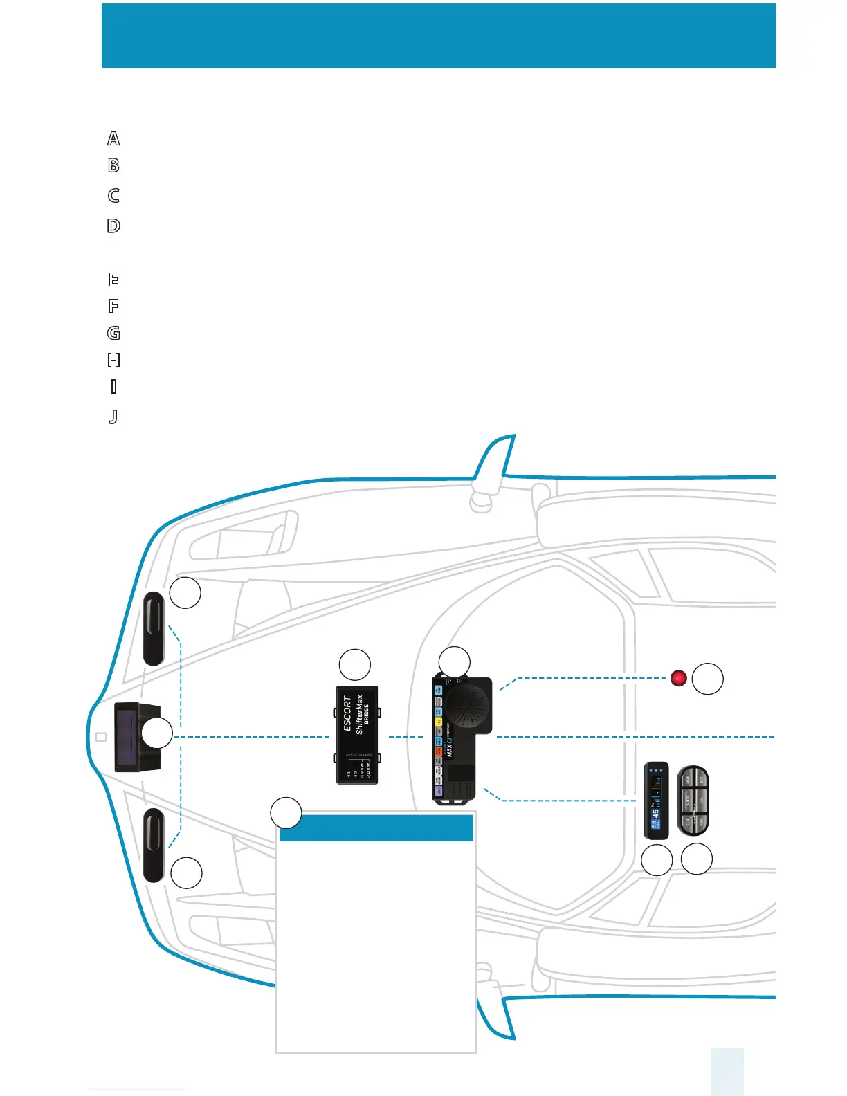
Installation Schematic Overview
Letter References For Components (Color Coded Connections To Interface)
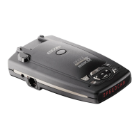
A Interface
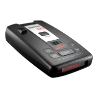
B Front Radar Receiver (White Stripe)
C Front ShifterMax Sensors (plug into ports 1 & 2 on ShifterMax Bridge Box)
D ShifterMax Bridge Box (plugs into Interface using supplied cable with no
stripe or shrink)
E GPS Antenna (Yellow Shrink)
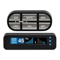
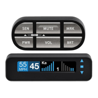
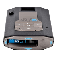
F Display Module (Orange Shrink)
G Control Module (Blue Shrink)
H Concealed Alert Indicator (Gray Shrink)
I Rear Radar Receiver (optional, included with ESCORT MAX Ci 360)
J Rear ShifterMax Sensors (optional, included with ESCORT MAX Ci 360)
A
B
C
D
F
G
H
C
ShifterMax Bridge Box
1 The Bridge Box is weatherproof so
it can be installed in the engine
compartment or under the dash.
2 Connect Front ShifterMax Sensors
to ports 1 and 2 of the Bridge Box.
3 Connect Rear ShifterMax Sensors
to ports 3 and 4 of the Bridge Box.
4 The Bridge Box connects to the
Interface using the supplied cable
with a 6 pin modular plug on one
end and a round shifter plug on
the other end.
D
 Loading...