2 Pin Definitions
2 Pin Definitions
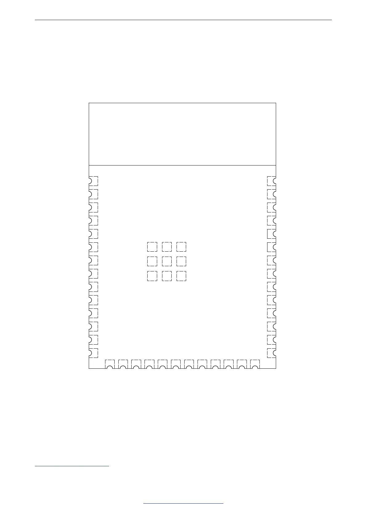
2.1 Pin Layout
The pin diagram is applicable for ESP32-S3-WROOM-1 and ESP32-S3-WROOM-1U, but the latter has no
keepout zone.
GND
3V3
EN
IO4
IO5
IO6
IO7
IO20
40
39
38
37
36
35
34
33
32
31
30
29
28
27
GND
IO1
IO2
TXD0
RXD0
IO42
IO41
IO40
IO39
IO38
IO37
IO36
IO35
IO0
41
GND
Keepout Zone
GND
GND GND GND
GND
GNDGNDGND
18
19
20
IO10
IO11
IO12
21
22
23
IO13
IO14
IO21
15
16
17
IO3
IO46
IO9
24
25
26
IO47
IO48
IO45
1
2
3
4
5
6
7
8
9
10
11
12
13
14
IO15
IO16
IO17
IO18
IO8
IO19
Figure 1: Pin Layout (Top View)
2.2 Pin Description
The module has 41 pins. See pin definitions in Table 2.
For explanations of pin names and function names, as well as configurations of peripheral pins, please refer to
ESP32-S3 Series Datasheet.
Espressif Systems 7
Submit Documentation Feedback
ESP32-S3-WROOM-1 & WROOM-1U Datasheet v0.6
 Loading...