Do you have a question about the Espressif ESP32-DevKitC V4 and is the answer not in the manual?
Lists different ESP32 modules like WROOM, SOLO, WROVER variants for user requirements.
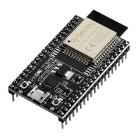
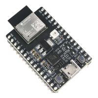
Describes main components like ESP32 module, EN button, Boot button, USB-to-UART bridge.
Details three mutually exclusive ways to power the board: Micro USB, 5V/GND, or 3V3/GND header pins.
Provides name and function of I/O header pins on both sides of the board, matching schematics.
Lists GPIO pin numbers, names, types, and functions for J1 and J3 connectors.
Details processor, Wi-Fi, Bluetooth, memory, and peripheral capabilities of the ESP32 module.
Guides users to set up the development environment and flash an example project onto the board.
Provides the physical dimensions (length, width, height) of the ESP32-DevKitC board.
The ESP32-DevKitC V4 is a versatile, small-sized development board designed for a wide range of user requirements, primarily featuring an ESP32 module at its core. This guide provides a comprehensive overview of how to get started with the board, detailing its components, interfaces, and controls, as well as power supply options and pin layouts.
At its heart, the ESP32-DevKitC V4 serves as a robust platform for developing and prototyping applications based on the ESP32 microcontroller. The board is designed to facilitate easy interfacing with various peripherals, making it suitable for both beginners and experienced developers. Its primary function is to provide a convenient way to access the ESP32's I/O pins, which are broken out to pin headers on both sides of the board. This allows developers to connect external components using jumper wires or mount the board directly onto a breadboard for more complex setups.
The board integrates a USB-to-UART Bridge chip, which is crucial for communication between a computer and the ESP32 module. This bridge enables firmware downloads and serial communication, providing transfer rates of up to 3 Mbps. This high-speed communication is essential for efficient development, allowing for quick flashing of new firmware and real-time debugging.
Power supply is a fundamental aspect of any development board, and the ESP32-DevKitC V4 offers flexible options. It can be powered via its Micro USB port, which also serves as the default power supply. Alternatively, users can provide power through 5V/GND or 3V3/GND header pins, catering to different project requirements and power sources. A 5V Power On LED indicates when the board is receiving power, whether from USB or an external supply, offering a visual confirmation of its operational status.
The I/O pins on the ESP32 module are extensively broken out to the board's pin headers, allowing for a wide array of functionalities. Developers can program the ESP32 to enable multiple functions such as Pulse Width Modulation (PWM), Analog-to-Digital Conversion (ADC), Digital-to-Analog Conversion (DAC), I2C, I2S, and SPI. This broad support for various communication protocols and peripheral interfaces makes the ESP32-DevKitC V4 highly adaptable for diverse applications, from simple sensor readings to complex control systems.
The board also includes essential control buttons: an EN (Reset) button and a Boot (Download) button. The EN button is used to reset the ESP32 module, which is often necessary during development for restarting the program or recovering from an error state. The Boot button, when held down while pressing EN, initiates the Firmware Download mode. This mode is critical for flashing new firmware onto the ESP32 through the serial port, enabling developers to update their applications or install different operating systems.
To accommodate a wide range of user needs and preferences, the ESP32-DevKitC V4 is available with different ESP32 modules, including ESP32-WROOM-DA, ESP32-WROOM-32E, ESP32-WROOM-32UE, ESP32-WROOM-32D, ESP32-WROOM-32U, ESP32-SOLO-1, ESP32-WROVER-E, and ESP32-WROVER-IE. This variety allows users to select the module that best fits their specific project requirements, whether it's for enhanced Wi-Fi performance, additional PSRAM, or other specialized features. Furthermore, the board can be purchased with either male or female pin headers, offering flexibility in how it integrates with other components and breadboards.
The ESP32-DevKitC V4 is designed with ease of use in mind, making it accessible for both beginners and experienced developers. The clear labeling of I/O pins and control elements simplifies the process of connecting peripherals and interacting with the board. The comprehensive pin layout tables, which include pin names, types (Power supply, Input, Output), and functions, are invaluable resources for understanding the capabilities of each pin and ensuring correct wiring.
One of the key usage features is the straightforward process for application development. After setting up the development environment, users can quickly flash example projects onto the board. The integration of the USB-to-UART bridge means that a single USB cable can handle both power and data communication, reducing clutter and simplifying the setup. This plug-and-play capability allows developers to get started with their projects without needing extensive external hardware.
The flexibility in power supply options is another significant usage feature. While the Micro USB port is the default and most convenient option, the availability of 5V/GND and 3V3/GND header pins allows for integration into systems where a dedicated power supply is preferred or required. This adaptability ensures that the board can be powered from various sources, such as battery packs for portable applications or regulated power supplies in more permanent installations. However, it is crucial to note the warning about providing power using only one option at a time to prevent damage to the board or the power supply source.
The inclusion of the EN and Boot buttons streamlines the development workflow. The EN button provides an easy way to reset the ESP32, which is frequently used during debugging and testing. The Boot button, in conjunction with the EN button, facilitates the firmware download process, allowing for rapid iteration and deployment of new code. This direct control over the board's operational modes enhances the efficiency of the development cycle.
The breakout of most ESP32 module pins to accessible headers is a core usage feature. This design choice maximizes the board's versatility, enabling developers to utilize the full range of the ESP32's capabilities. Whether it's connecting sensors, actuators, or other microcontrollers, the clearly defined I/O pins simplify the hardware integration process. The ability to program these pins for various functions like PWM, ADC, DAC, I2C, I2S, and SPI means that the board can adapt to almost any embedded application.
Furthermore, the availability of different ESP32 modules and pin header types (male or female) provides customization options that cater to specific project needs. For instance, a developer might choose a module with integrated PSRAM for memory-intensive applications or opt for female headers to directly plug in jumper wires without additional connectors. This modularity enhances the board's utility and broadens its applicability across different use cases.
While the ESP32-DevKitC V4 is generally robust, there are specific maintenance considerations that users should be aware of to ensure optimal performance and longevity. One notable aspect relates to the internal communication pins and their usage. The pins D0, D1, D2, D3, CMD, and CLK are internally used for communication between the ESP32 and SPI flash memory. These pins are grouped near the USB connector, and it is advised to avoid using them for external connections. Disrupting these pins can interfere with access to the SPI flash memory or SPI RAM, potentially leading to unstable operation or system failures. This guidance is a crucial maintenance tip for preventing common issues during development.
Another important maintenance detail concerns the GPIO16 and GPIO17 pins. These pins are available for general use only on boards equipped with ESP32-WROOM and ESP32-SOLO-1 modules. For boards featuring ESP32-WROVER modules, these pins are reserved for internal use. This distinction highlights the importance of knowing which ESP32 module is integrated into the DevKitC V4 board to avoid attempting to use pins that are not externally available or are internally occupied, which could lead to unexpected behavior or system conflicts.
A specific maintenance note addresses a potential issue with component C15 on earlier ESP32-DevKitC V4 boards. This component, if present, might cause the board to boot into Download mode unexpectedly or impact the signal if a clock is output on GPIO0. In such cases, the recommended maintenance action is to remove component C15. The manual provides a visual guide to locate C15, highlighted in yellow, making it easy for users to identify and address this specific issue. This proactive maintenance step ensures stable operation and prevents potential disruptions during development.
General maintenance practices also apply to the ESP32-DevKitC V4. Before powering up the board, it is essential to inspect it for any obvious signs of damage. This simple check can prevent further issues and ensure that the board is in good working condition. Proper handling and storage of the board, protecting it from electrostatic discharge, moisture, and physical impact, will contribute significantly to its lifespan.
The clear documentation of the board's components, pin functions, and power supply options serves as a valuable maintenance tool. By understanding the internal workings and recommended usage guidelines, developers can troubleshoot issues more effectively and maintain the board in optimal condition. For instance, if power issues arise, consulting the power supply options and the 5V Power On LED status can help diagnose the problem. Similarly, if communication errors occur, reviewing the USB-to-UART bridge description and related documents can guide the troubleshooting process.
In summary, the ESP32-DevKitC V4 is a well-documented and versatile development board designed for a broad spectrum of applications. Its functional description highlights its core capabilities as an ESP32-based platform with extensive I/O breakout, flexible power options, and essential control buttons. The usage features emphasize its ease of development, streamlined workflow, and adaptability to various project needs through module and header type choices. Maintenance features focus on critical guidelines for pin usage, module-specific pin availability, and a specific component removal for older boards, all aimed at ensuring reliable and long-term operation.
| Type | Development Board |
|---|---|
| Microcontroller | ESP32 |
| Clock Speed | 240 MHz |
| SRAM | 520 KB |
| Flash Memory | 4 MB |
| Wi-Fi | 802.11 b/g/n |
| Operating Voltage | 3.3 V |
| Input Voltage | 5 V |
| Chip | ESP32 |
| CPU | Dual-core 32-bit LX6 |
| Bluetooth | Bluetooth 4.2 |
| Interfaces | SPI, I2C, I2S, UART |
| ADC | 12-bit SAR ADC |
| DAC | 2 x 8-bit DAC |
| SPI | 4 |
| I2C | 2 |
| I2S | 2 |
| UART | 3 |