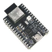
The ESP32-C3-DevKitM-1 is an entry-level development board designed for ease of use and versatility in application development. At its core, the board integrates the ESP32-C3-MINI-1 module, a compact Wi-Fi and Bluetooth LE combo module. This module is notable for its small package size, achieved by embedding the 4 MB flash memory directly into the ESP32-C3FN4 chip, rather than integrating it separately into the module. This design choice contributes to the overall compact footprint of the development board.
Function Description:
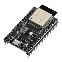
The primary function of the ESP32-C3-DevKitM-1 is to provide a robust platform for developing applications that leverage Wi-Fi and Bluetooth LE connectivity. It serves as a bridge between the powerful ESP32-C3FN4 chip and external peripherals, making it suitable for a wide range of IoT projects, embedded systems, and rapid prototyping. The board breaks out most of the I/O pins from the ESP32-C3-MINI-1 module to pin headers on both sides, facilitating easy interfacing with external components. Developers have the flexibility to connect peripherals using jumper wires or mount the entire ESP32-C3-DevKitM-1 onto a breadboard for more complex setups.
Important Technical Specifications:
- Core Module: ESP32-C3-MINI-1, featuring the ESP32-C3FN4 chip.
- Connectivity: Integrated Wi-Fi and Bluetooth LE functions.
- Flash Memory: 4 MB embedded flash within the ESP32-C3FN4 chip.
- Power Supply Options:
- Micro USB port (recommended, default power supply).
- 5V and GND header pins.
- 3V3 and GND header pins.
- Power Regulator: A 5V to 3.3V LDO (Low-Dropout Regulator) converts the 5V input to a stable 3.3V output for the module.
- USB-to-UART Bridge: A single USB-UART bridge chip provides data transfer rates up to 3 Mbps, enabling communication between the ESP32-C3FN4 chip and a computer.
- RGB LED: An addressable RGB LED (WS2812) driven by GPIO8, offering visual feedback and customization options.
- I/O Connectors: All available GPIO pins (except those used by the SPI bus for flash) are broken out to pin headers, allowing extensive peripheral connectivity.
- Buttons:
- Reset Button: Restarts the system.
- Boot Button: Used in conjunction with the Reset button to initiate Firmware Download mode for flashing new firmware via the serial port.
Usage Features:
- Ease of Interfacing: The breakout of most I/O pins to standard pin headers simplifies the connection of sensors, actuators, and other external components. This design choice caters to both beginners and experienced developers, allowing for quick prototyping and experimentation.
- Breadboard Compatibility: The form factor of the ESP32-C3-DevKitM-1 allows it to be easily mounted on a breadboard, providing a flexible environment for circuit building and testing without permanent soldering.
- Firmware Download Mode: The combination of the Boot and Reset buttons provides a straightforward mechanism for entering Firmware Download mode, essential for updating or flashing new application firmware onto the ESP32-C3FN4 chip.
- USB Communication: The integrated Micro-USB port serves a dual purpose: providing power to the board and establishing a communication interface between the development board and a host computer. This simplifies the development workflow, as a single cable handles both power and data transfer for programming and debugging.
- Visual Feedback: The onboard RGB LED (WS2812) offers a programmable visual indicator, which can be used for debugging, status reporting, or creating interactive light patterns in applications.
- Flexible Powering: With three distinct ways to power the board, developers can choose the most convenient method based on their setup. The Micro USB port is recommended for its simplicity and common availability.
- Comprehensive Documentation: The user guide provides a detailed description of components, pin layouts, and setup instructions, ensuring a smooth onboarding experience for developers.
Header Block Pin Descriptions (J1 and J3):
The board features two main header blocks, J1 and J3, with various pins serving different functions:
J1 Pins:
- GND (Pins 1, 6, 8, 12, 15): Ground connections.
- 3V3 (Pins 2, 3): 3.3 V power supply outputs.
- IO2 (Pin 4): GPIO2, ADC1_CH2, FSPIQ (Input/Output/Tristate).
- IO3 (Pin 5): GPIO3, ADC1_CH3 (Input/Output/Tristate).
- RST (Pin 7): CHIP_PU (Input), chip enable/reset.
- IO0 (Pin 9): GPIO0, ADC1_CH0, XTAL_32K_P (Input/Output/Tristate).
- IO1 (Pin 10): GPIO1, ADC1_CH1, XTAL_32K_N (Input/Output/Tristate).
- IO10 (Pin 11): GPIO10, FSPICS0 (Input/Output/Tristate).
- 5V (Pins 13, 14): 5 V power supply inputs.
J3 Pins:
- GND (Pins 1, 4, 7, 12, 15): Ground connections.
- TX (Pin 2): GPIO21, U0TXD (Input/Output/Tristate), UART transmit.
- RX (Pin 3): GPIO20, U0RXD (Input/Output/Tristate), UART receive.
- IO9 (Pin 5): GPIO9 (Input/Output/Tristate).
- IO8 (Pin 6): GPIO8 (Input/Output/Tristate), drives the RGB LED.
- IO7 (Pin 8): GPIO7, FSPID, MTDO (Input/Output/Tristate).
- IO6 (Pin 9): GPIO6, FSPICLK, MTCK (Input/Output/Tristate).
- IO5 (Pin 10): GPIO5, ADC2_CH0, FSPIWP, MTDI (Input/Output/Tristate).
- IO4 (Pin 11): GPIO4, ADC1_CH4, FSPIHD, MTMS (Input/Output/Tristate).
- IO18 (Pin 13): GPIO18 (Input/Output/Tristate).
- IO19 (Pin 14): GPIO19 (Input/Output/Tristate).
Maintenance Features:
- Robust Design: The board is designed for development and prototyping, implying a certain level of durability for repeated connections and disconnections.
- Clear Component Labeling: Key components like the ESP32-C3-MINI-1 module, RGB LED, USB-to-UART Bridge, Reset Button, Boot Button, and Micro-USB Port are clearly labeled on the board, aiding in identification and troubleshooting.
- Power-On LED: A dedicated 5V Power On LED illuminates when USB power is connected, providing immediate visual confirmation that the board is receiving power, which is helpful for initial setup and debugging power issues.
- Software Setup Guidance: The manual emphasizes a clear software setup process, directing users to "Get Started" and "Installation Step by Step" sections. This structured approach helps users quickly establish their development environment and flash application examples, minimizing potential software-related maintenance issues.
- Pre-shipment Inspection: Users are advised to ensure the board is in good condition with no obvious signs of damage before powering it up, promoting early detection of potential hardware faults.
- Standardized Interfaces: The use of a Micro-USB port and standard pin headers means that common cables and jumper wires can be used, simplifying replacement of accessories if needed.
In summary, the ESP32-C3-DevKitM-1 is a well-rounded development board that combines powerful Wi-Fi and Bluetooth LE capabilities with user-friendly features, making it an excellent choice for a wide array of embedded and IoT applications. Its compact size, flexible power options, and comprehensive I/O breakout ensure a versatile and efficient development experience.