C 3- 400 I nstallation I nstructions and C onnection G uide
1. Cautions
1
2
3
Please note the following cautions. Mis-operation may lead to personal injury or
equipment failure:
1)Do not energize the system before installation is complete; never carry out
installation activities when the system is energized.
2)All peripheral devices must be grounded.
3)The conduits of wires under relay must be matched with metaled conduits, other
wires can use PVC conduits.
4)It is strongly recommended that the length of exposed part of any connection cable
should not be longer than 4 mm. Professional clamping tools may be used to avoid
unintentional c
ontact of exposed wires to avoid short-circuit or communication failure.
5)It is recommended that card readers and buttons be installed at height of 1.4m-1.5m
above ground.
6)It is recommended to use the power supply for control panel, and external power
supply for each lock.
7)The appliance shall be installed and wired in accordance with national electrical
code and by qualified personnel only.
Descr iption of n or mal w or k ing state:
Connect the system to the power supply. If the system works properly, the POWER
indicator (red) is lit constantly and the RUN indicat
or (green) flashes.
V al ve r egulated l ead-acid batter y:
Constant voltage charge voltage regulation
Cycle use : 14.5V~14.9V(25)
Initial current: less than 2.88A
Standby use: 13.6V~13.8V(25)
Capacity: 12V, 7.2Ah/20hr,
Battery Type: LC-RA127R2T1
C aution:
Do not charge in a gas tight container.
Do not short the battery terminals.
Do not incinerate
Flush with water at once if contact is made with
electrolyte (Acid)
Do not attempt to disassemble the battery.
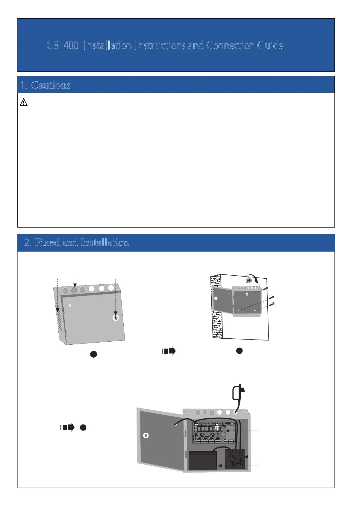
Get through the thread hole Fixed case
Control panel
The
charging
circuit board
Backup battery
Heat
dissipation
hole Thread hole Key hole
Wiring the Control Panel, The Charging
Circuit Board and Backup Battery
POWER
2. Fixed and Installation
11
1
1
T
X
RX
TX
RX
A
C
T
LIN
K
POWER
C
AR
D
R
U
N
V+
G
N
D
IN
BUTTON4
G
N
D
IN
BUTTON3
G
N
D
IN
BUTTON2
GND
+
1
2
V
WD1
WD0
READER4
G
L
E
D
B
EE
P
G
N
D
+
1
2
V
WD1
WD0
READER3
GL
E
D
BEE
P
G
N
D
+
1
2
V
WD1
W
D
0
READER2
GLE
D
B
E
E
P
POWER
PC
LAN
N
C
N
C
NC
NC
COM
C
O
M
COM
CO
M
NO
N
O
NO
N
O
COM
COM
C
O
M
COM
N
O
NO
N
O
N
O
NC
NC
N
C
NC
LOCK1
LOCK2
LOCK4
LOCK3
G
N
D
G
N
D
G
N
D
G
N
D
SE
N
S
E
N
SE
N
SE
N
V-
AUX1 AUX2
AUX3
AUX4
EXT
BUTTON1
READER1
+
1
2
V
G
N
D
W
D
1
WD0
G
LE
D
BEE
P
+
1
2
V
G
N
D
48
5
-
48
5
+
G
N
D
G
N
D
G
ND
G
N
D
IN
I
N
I
N
IN
IN
GND
G
N
D
4
8
5-
4
8
5+
AUXOUT1 AUXOUT2 AUXOUT3 AUXOUT4
LOCK
G
N
D
+
1
2
V
1 2 3 4
ON
5 6 7 8
SD
Ca
rd
Adv ance d Acc es
s Co ntrol
 Loading...