4. LED Indicators, Wires, Auxiliary Input And Output
Notes:
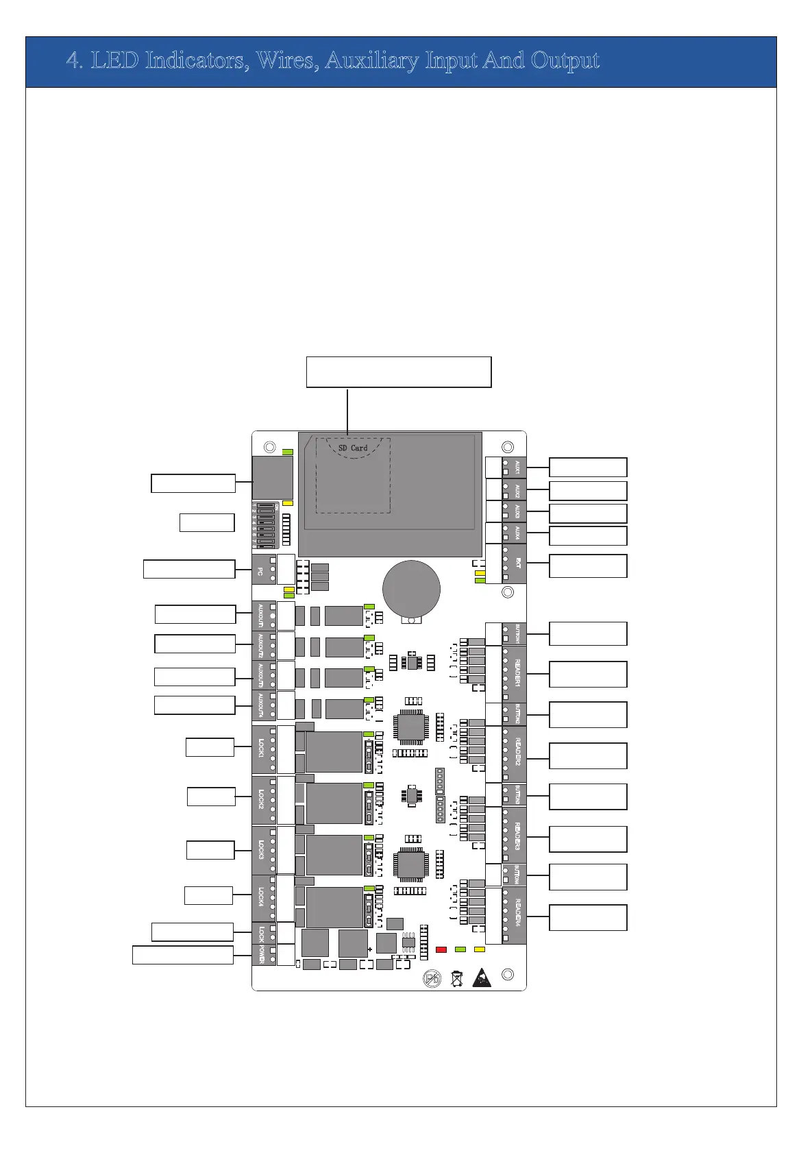
1)Meaning of LED indicators:
LINK indicator(green): always(green) indicates TCP/IP
ACT indicator(yellow): flashing indicates data is in transmitting
TX indicator(yellow): flashing indicates it is sending data through
RX indicator(green): flashing indicates it is receiving data through
Auxiliary output indicator(green):always(green) indicates it is in use.
Lock indicator(green):always(green) indicates lock is open.
POWER indicator(red):always(red) indicates control panel is power on.
RUN indicator(green):its flashing indicates the system works normally.
CARD indicator(yellow):its flashing indicates card is punched on reader.
A Use 2-conducotor power cord
2)Recommended use of wires:
3)The auxiliary input may be connnected to infrared body detectors,
4)The auxiliary output may be connected to door bells,alarms,etc.
B Use 6-conductor wire between wiegand reader and control panel
C Use 4-conducotor lock power cord (RVV 4*0.75mm)
D Use 2-conducotor switch power cord(RVV 2*0.5mm)
communication is proper;
alam switches,etc.
through TCP/IP communication.
RS485 communication.
RS485 communication.
(RVVP 6*0.5mm) (Choose the approrciate cord for the interface
you connect, such as 6,8,10 cord.)
A
A
C
C
C
C
D
D
D
D
D
D
D
D
D
B
D
B
D
B
D
B
PC RS485 interface
Ethernet interface
Dip switch
Auxiliary output1
Auxiliary output2
Auxiliary output3
Auxiliary output4
Lock1
Lock2
Lock3
Lock4
Power of lock
Power of control panel
1
1
1
1
TX
RX
TX
RX
ACT
LINK
POWER
CARD
RUN
GND
IN
BUTT
ON4
GND
IN
BUTTON3
GND
IN
BUTT
O
N
2
GND
WD1
WD0
R
EA
D
ER
4
GLED
BEEP
GND
WD1
WD0
R
EA
D
ER
3
GLED
BEEP
GND
WD1
WD0
R
E
A
D
E
R2
GLED
BEEP
PO
W
ER
P
C
LAN
NC
NC
NC
NC
COM
COM
COM
COM
NO
NO
NO
NO
COM
COM
COM
COM
NO
NO
NO
NO
NC
NC
NC
NC
L
O
CK
1
L
OC
K
2
L
OC
K
4
L
O
C
K
3
GND
GND
GND
GND
SEN
SEN
SEN
SEN
AUX1
A
UX2
A
UX3
A
UX4
E
XT
BUTTO
N
1
R
E
AD
ER
1
GND
WD1
WD0
GLED
BEEP
GND
GND
GND
GND
GND
IN
IN
IN
IN
IN
GND
GND
AUXOUT
1
AU
X
OUT2 A
U
XOU
T
3 A
U
XOUT4
L
OC
K
GND
SD Card
Advanced Access Control
485+
485-
485+
485-
+12V
+12V
+12V
+12V
+12V
V+
V-
ON
1
4
6
2
3
5
7
8
Auxiliary input1
Auxiliary input2
Auxiliary input3
Auxiliary input4
Extended
RS485 output
1# Door Button
1# Door
W iegand reader
2# Door Button
2# Door
W
iegand reader
3# Door Button
3# Door
W
iegand reader
4#Door Button
4# Door
W iegand reader
Note:
AUX Input (1-4) connect to
the infrared human body
induction, wireless exit
button, windows sensor
with dry contact (no
voltage);
Note:
AUX Input (1-4) connect
way is same
Note:
Output Electrical
Parameters:
Rated Voltage:12V(DC)
Rated Current: 0.5A
Note:
1、Door button (1-4)
connect to Exit button with
dry contact.(no voltage);
2、Wiegand Reader (1-4)
connect to WG Reader;
Port (+12V)Output
Electrical Parameters:
Rated Voltage: 12V(DC)
Rated Current: 0.5A
Port (BEEP GLED) Output
Electrical Parameters:
Rated Volta
ge: 5V(DC)
Raged Current: 0.5mA
Note:
AUX Output (1-4)
connect to alarm,door
bell and so on;
Port (NO,COM,NC)
Electrical Parameters:
MAX Voltage:
36V(DC)
MAX Current: 1.25A
Note:
AUX Output (1-4)
connect way is same
SD Card Interface;
Function: Backup Access Control Logs
Note:
Lock Power Input
Electrical Parameters:
Rated Voltage: 36V(DC)
Rated Current: 2A
Device Power Input
Electrical Parameters:
Rated Voltage: 12V(DC)
Rated Current: 2A
Note:
Lock(1-4):
Port (SEN)connect to door
sensor single with dry
contact (no voltage
);
Port (NO, COM, NC)
Electrical Parameters:
MAX Voltage: 36V(DC)
MAX Current: 2A
Note:
When you select Wet mode,
The power is Lock power,
Lock (1-4) total load don’t
more than Lock power Rated
current (2A)
Note:
Lock (1-4) connect way is
same
 Loading...